CONDENSER (for 2WD) INSTALLATION

-
INSTALL COOLER DRYER
-
Using pliers, install the cooler dryer.
-
Apply a sufficient amount of compressor oil to the contact surfaces of a new O-ring and the cap.
Compressor oil ND-OIL 8 or equivalent -
Install the O-ring to the cap.
-
Using a 14 mm socket hexagon wrench, install the cap to the modulator.
- Torque:
- 2.9 N*m { 30 kgf*cm, 26 in.*lbf }
-
-
INSTALL COOLER CONDENSER ASSEMBLY
-
Install the cooler condenser assembly with the 4 bolts.
- Torque:
- 6.0 N*m { 61 kgf*cm, 53 in.*lbf }
-
-
CONNECT LIQUID TUBE SUB-ASSEMBLY A
-
Remove the attached vinyl tape from the tube and the connecting part of the cooler condenser.
-
Sufficiently apply compressor oil to a new O-ring and the fitting surface of the tube joint.
Compressor oil ND-OIL 8 or equivalent -
Install the O-ring to the liquid tube sub-assembly A.
-
Connect the liquid tube sub-assembly A to the cooler condenser with the bolt.
- Torque:
- 5.4 N*m { 55 kgf*cm, 48 in.*lbf }
Note
-
When tightening the bolt, do not allow any tools to contact the tube.
-
When tightening the bolt, hold a part of the tube near the connector.
-
-
CONNECT DISCHARGE HOSE SUB-ASSEMBLY
-
Remove the attached vinyl tape from the hose and the connecting part of the cooler condenser.
-
Sufficiently apply compressor oil to a new O-ring and the fitting surface of the hose joint.
Compressor oil ND-OIL 8 or equivalent -
Install the O-ring to the discharge hose sub-assembly.
-
Connect the discharge hose sub-assembly to the cooler condenser with the bolt.
- Torque:
- 5.4 N*m { 55 kgf*cm, 48 in.*lbf }
Note
-
When tightening the bolt, do not allow any tools to contact the hose.
-
When tightening the bolt, hold a part of the hose near the connector.
-
-
INSTALL HOOD LOCK ASSEMBLY
-
Install the hood lock assembly to the hood lock control cable.
-
-
INSTALL HOOD LOCK CONTROL CABLE COVER
-
Connect the wire harness clamp.
-
Connect the hood lock control cable to the hood lock control cable cover.
-
Attach the guide to install the hood lock control cable cover.
-
-
INSTALL RADIATOR UPPER SUPPORT SUB-ASSEMBLY
-
Connect the 3 connectors and attach the 5 wire harness clamps to connect the wire harness.
-
Install the radiator upper support with the 5 bolts.
- Torque:
- 8.0 N*m { 82 kgf*cm, 71 in.*lbf }
-
-
CONNECT HOOD LOCK ASSEMBLY
-
Connect the connector.
-
Connect the hood lock assembly with the 2 bolts and lock nut.
- Torque:
- 8.0 N*m { 82 kgf*cm, 71 in.*lbf }
-
Install the lock nut cap.
-
-
CONNECT HOOD LOCK CONTROL CABLE COVER
-
Connect the hood lock control cable cover with the 3 screws and attach the claw.
-
-
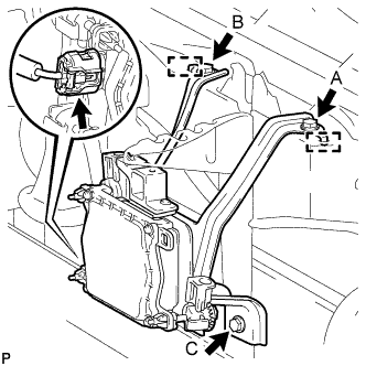
INSTALL MILLIMETER WAVE RADAR SENSOR ASSEMBLY (w/ Dynamic Radar Cruise Control System)
-
Connect the connector.
-
Attach the 2 guides and install the millimeter wave radar sensor assembly with the 3 bolts in alphabetical order.
- Torque:
- 5.5 N*m { 56 kgf*cm, 49 in.*lbf }
-
-
INSTALL FRONT BUMPER COVER
-
ADD COMPRESSOR OIL
-
When performing work on air conditioning parts, follow the oil guidelines below in order to protect the cooler compressor.
Part and Condition Oil Level (cc) Work Procedure Compressor replacement -100 to -120 Drain oil from new compressor Condenser replacement 35 to 55 Fill oil into replacement part Evaporator replacement 40 to 60 A/C pipe replacement High pressure 5 to 25 Low pressure When discharging refrigerant gas quickly 30 to 50 While applying vacuum, use manifold gauge to fill oil from low pressure side valve
-
-
CHARGE REFRIGERANT
- SST
- 09985-20010 ( 09985-02130, 09985-02150, 09985-02090, 09985-02110, 09985-02010, 09985-02050, 09985-02060, 09985-02070 )
-
Perform vacuum purging using a vacuum pump.
-
Charge refrigerant HFC-134a (R134a).
Standard Destination Air Conditioning Type Refrigerant Charging Amount except G.C.C Countries w/o Rear Cooler 550 +/-50 g (19.4 +/-1.8 oz.) w/ Rear Cooler 700 +/-30 g (24.7 +/-1.1 oz.) G.C.C Countries w/o Rear Cooler 750 +/-30 g (26.5 +/-1.1 oz.) w/ Rear Cooler 1000 +/-50 g (35.3 +/-1.8 oz.) 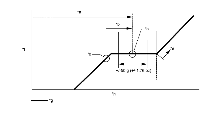
Text in Illustration *a Amount to be charged *b Charge 100 g (3.53 oz) *c Mean value in proper range *d Point where bubbles disappear *e Overcharged *f Pressure *g Sub-cool system *h Refrigerant amount Note
-
Do not operate the cooler compressor before charging refrigerant as the cooler compressor will not work properly without any refrigerant, and will overheat.
-
Approximately 200 g (7.05 oz.) of refrigerant may need to be charged after bubbles disappear. The refrigerant amount should be checked by measuring its quantity, and not with the sight glass.
-
-
WARM UP ENGINE
-
Warm up the engine at less than 1850 rpm for 2 minutes or more after charging the refrigerant.
Note
Be sure to warm up the compressor when turning the A/C switch ON after removing and installing the cooler refrigerant lines (including the compressor) to prevent damage to the compressor.
-
-
CHECK FOR LEAKAGE OF REFRIGERANT
-
After recharging the refrigerant gas, check for refrigerant gas leakage using a halogen leak detector.
-
Perform the operation under these conditions:
-
Stop the engine.
-
Secure good ventilation (the halogen leak detector may react to volatile gases other than refrigerant, such as evaporated gasoline or exhaust gas).
-
Repeat the test 2 or 3 times.
-
Make sure that some refrigerant remains in the refrigeration system.
Tech Tips
When compressor is off:
approximately 392 to 588 kPa (4 to 6 kgf/cm2, 57 to 85 psi)
-
-
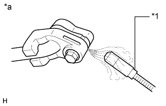
Text in Illustration *1 Halogen Leak Detector *a Check for Leakage Using a halogen leak detector, check the refrigerant line for leakage.
-
If a gas leak is not detected on the drain hose, remove the blower motor control (blower resistor) from the cooling unit. Insert the halogen leak detector sensor into the unit and perform the test.
-
Disconnect the connector and wait for approximately 20 minutes. Bring the halogen leak detector close to the pressure switch and perform the test.
-
-
ADJUST MILLIMETER WAVE RADAR SENSOR ASSEMBLY (w/ Dynamic Radar Cruise Control System)
CAUTION:
Exposure to radio frequency emissions is hazardous to your health. It is hazardous to be within 20 cm (7.87 in.) of the device's radio frequency aperture.
Note
-
This device complies with FCC radio frequency emission regulations.
-
Perform measurements on a level surface.
-
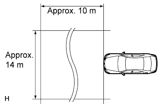
Make sure that no large pieces of metal are within a 10 m (32.8 ft.) x 14 m (45.9 ft.) area in front of the vehicle. If possible, the surrounding area should also be free of large metal objects.
-
Before adjusting the radar beam axis, prepare the vehicle as follows.
-
Check the tire pressure and adjust it if necessary.
-
Remove all excess weight from the vehicle (luggage, heavy objects, etc.).
-
-
w/ Air Suspension:
Adjust the vehicle's height to the standard height.
-
Check and adjust the vertical direction of the radar sensor.
-
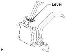
Remove dust, oil and foreign matter from the radar sensor's level rack.
-
Set a level on the radar sensor's level rack.
-
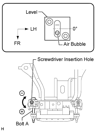
Check that the level's air bubble is within the red frame.
OK Level's air bubble is within red frame. If the bubble is not within the red frame, use a hexagon wrench to adjust bolt A until the level's air bubble is within the red frame.
Tech Tips
-
The adjustable range within the red frame of the level is +/-0.2°.
-
The target angle is +0.2° (upward angle of 0.2°).
Result Adjustment Direction Adjustment Procedure Adjustment Angle Vertical adjustment
-
Upward direction: Turn bolt A in minus (-) direction
-
Downward direction: Turn bolt A in plus (+) direction
For 1 complete turn of screwdriver, sensor moves about 0.12° -
-
-
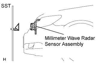
Adjust the reflector height.
-
Adjust the reflector so that the center of the SST reflector is the same height as the millimeter wave radar sensor.
- SST
- 09870-60000 ( 09870-60010 )
- 09870-60040
Tech Tips
Prepare a 10 m (32.8 ft.) string with a sharp-pointed weight (plumb bob) and a 5 m (16.4 ft.) tape measure.
-
-
Place the reflector.
-
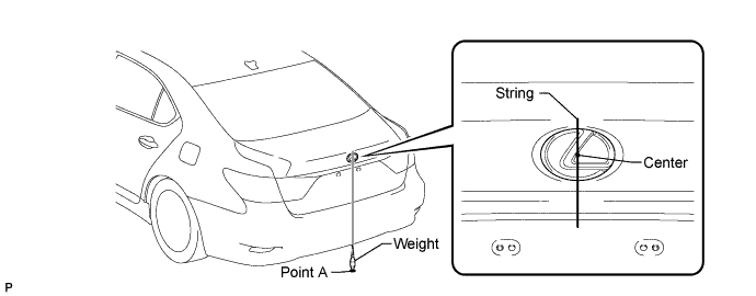
From the center of the front bumper (center of the emblem), hang a weight with a pointed tip, and mark point B on the ground.
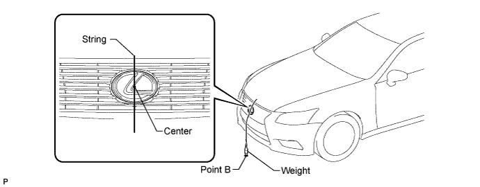
-
From the center of the rear bumper (center of the emblem), hang a weight with a pointed tip, and mark point A on the ground.
-
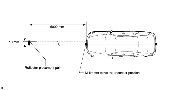
Using a piece of string that uses point A as a starting point and that passes through point B, make a straight line on the ground ahead of the vehicle 5 m (16.4 ft.) or more from point B.
Tech Tips
-
Make sure to secure the string (using tape, etc.) when it is taut.
-
Lightly flick the string with your fingers several times to confirm that the string is aligned above point B.
-
-
Using a tape measure, measure 10 mm (0.394 in.) to the left of the 5000 mm (16.4 ft.) position. Place the reflector at that position.
Note
Perform the operation as precisely as possible.
-
-
Check the radar beam axis.
-
When using the intelligent tester:
-
Connect the intelligent tester to the DLC3.
-
Turn the engine switch on (IG).
-
Turn the intelligent tester main switch ON and turn the cruise control main switch ON.
-
Select "Auto" from the intelligent tester display screen. *1
-
Select "Radar Cruise" from the display screen.
-
Select the appropriate menu item.
-
For vehicles with lane recognition camera: select "w/ LKA System" from the display screen.
-
For vehicles without lane recognition camera: select "w/o LKA System" from the display screen.
-
Select "Radar Cruise" from the display screen.
-
Select "Utility" from the display screen.
-
Select "Beam Axis Adjustment" from the display screen.
-
Select "Next".
-
Select "Next".
-
Select "Next".
Note
-
Turn the cruise control main switch ON before pressing Next.
-
Make sure there is a distance of at least 20 cm (7.87 inches) between the radar sensor and any nearby individuals.
CAUTION:
Do not come within 20 cm (7.87 inches) of the radar sensor.
-
-
Check the following items on the laser cruise divergence data screen.
CAUTION:
While using the intelligent tester's beam axis adjustment mode, the actual direction and angle of the radar sensor may be different from the intelligent tester's data. In such a case, the deviation is displayed on the combination meter's multi-information display.
-
Confirm that the distance value is approximately 5 m (16.4 ft.).
Tech Tips
-
A value between 0.0 and 6.3 m (20.7 ft.) is indicated.
-
If the distance is 0 m (0 ft.), the sensor cannot detect the target. Reconfirm that there is no metal in the specified area in front of the vehicle (refer to the NOTICE at the beginning of this adjustment procedure).
-
-
Confirm that the left/right side value is between 0.0 and 6.3°.
Tech Tips
If the distance is 0 m (0 ft.), the sensor cannot detect the target. Reconfirm that there is no metal in the specified area in front of the vehicle (refer to the NOTICE at the beginning of this adjustment procedure).
-
-
-
Check and adjust the horizontal direction of the radar sensor.
-
Check that the divergence of the radar beam axis is 0°.
Standard 0° (Both right and left) If the axis is not as specified, use a hexagon wrench to adjust bolt B until the divergence of the radar beam axis is 0°.
-
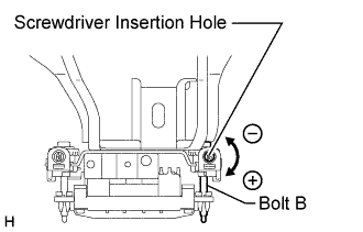
Based on the measured divergence of the beam axis, turn and adjust bolt B for horizontal adjustment of the millimeter wave radar sensor using a hexagon wrench.
Result Adjustment Direction Adjustment Procedure Adjustment Angle Horizontal adjustment
-
Right direction: Turn bolt B in plus (+) direction
-
Left direction: Turn bolt B in minus (-) direction
For 1 complete turn of screwdriver, sensor moves about 0.07° Tech Tips
If the value does not change to 0°, it is possible that the sensor is aiming at something different. Reconfirm that there are no reflective materials in the surrounding area.
-
-
Select "Next". The driving learning value is automatically reset.
Tech Tips
A buzzer will sound for 10 seconds.
-
Disconnect the intelligent tester from the DLC3.
-
-
Recheck and readjust the vertical direction of the radar sensor.
-
Set a level on the radar sensor's level rack.
-
Check that the level's air bubble is within the red frame.
OK Level's air bubble is within the red frame. If the bubble is not within the red frame, use a hexagon wrench to adjust bolt A until the level's air bubble is within the red frame.
Tech Tips
-
The adjustable range within the red frame is +/-0.2°.
-
The target angle is +0.2° (upward angle of 0.2°).
Result Adjustment Direction Adjustment Procedure Adjustment Angle Vertical adjustment
-
Upward direction: Turn bolt A in minus (-) direction
-
Downward direction: Turn bolt A in plus (+) direction
For 1 complete turn of screwdriver, sensor moves about 0.12° -
-
-
-
INSTALL NO. 1 ENGINE UNDER COVER
-
Install the No. 1 engine under cover with the 13 screws and 7 clips.
-
-
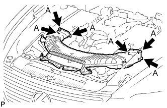
INSTALL NO. 1 AIR CLEANER INLET
-
Align the holes with the connection areas labeled A, and attach the No. 1 air cleaner inlet.
-

Install the No. 1 air cleaner inlet with the 2 bolts.
- Torque:
- 5.0 N*m { 51 kgf*cm, 44 in.*lbf }
-
-
INSTALL V-BANK COVER SUB-ASSEMBLY