CONDENSER (for 2WD) REMOVAL

-
RECOVER REFRIGERANT FROM REFRIGERATION SYSTEM
- SST
- 09985-20010 ( 09985-02130, 09985-02150, 09985-02090, 09985-02110, 09985-02010, 09985-02050, 09985-02060, 09985-02070 )
-
Start the engine.
-
Turn the A/C switch ON.
-
Operate the cooler compressor with an engine speed of approximately 1,000 rpm for 5 to 6 minutes to circulate the refrigerant and collect the compressor oil remaining in each component into the cooler compressor.
-
Stop the engine.
-
Recover the refrigerant from the A/C system using a refrigerant recovery unit.
-
REMOVE FRONT BUMPER COVER
-
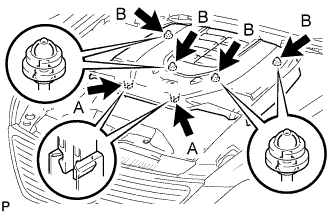
REMOVE V-BANK COVER SUB-ASSEMBLY
-
While using both hands, lift the rear side of the cover upwards to detach the 4 clips B. Slide the cover towards the front of the vehicle to detach the 2 clips labeled A, and remove the V-bank cover sub-assembly.
Note
The V-bank cover sub-assembly may be damaged if its front and rear are lifted at the same time.
-
-
REMOVE NO. 1 AIR CLEANER INLET

-
Remove the 2 bolts.
-
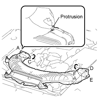
Hold the No. 1 air cleaner inlet by the protrusions labeled A and labeled B, and detach the connections.
-
Rotate the No. 1 air cleaner inlet as shown in the illustration to detach the protrusion labeled C.
-
Hold the air cleaner inlet by the protrusions labeled D and labeled E, and detach the connections.
-
Rotate the No. 1 air cleaner inlet as shown in the illustration to detach the protrusion labeled F.
-
-
REMOVE NO. 1 ENGINE UNDER COVER
-
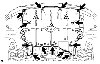
Remove the 13 screws, 7 clips and No. 1 engine under cover.
-
-
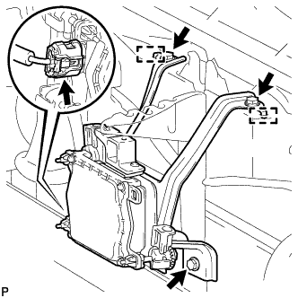
REMOVE MILLIMETER WAVE RADAR SENSOR ASSEMBLY (w/ Dynamic Radar Cruise Control System)
-
Disconnect the connector.
-
Remove the 3 bolts.
-
Detach the 2 guides and remove the millimeter wave radar sensor assembly.
-
-
DISCONNECT HOOD LOCK CONTROL CABLE COVER
-
Remove the 3 screws and detach the claw to disconnect the hood lock control cable cover.
-
-
DISCONNECT HOOD LOCK ASSEMBLY
-
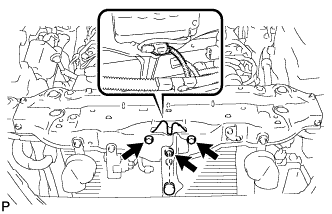
Remove the lock nut cap and lock nut.
-
Remove 2 bolts and disconnect the hood lock assembly.
-
Disconnect the connector.
-
-
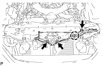
REMOVE RADIATOR UPPER SUPPORT SUB-ASSEMBLY
-
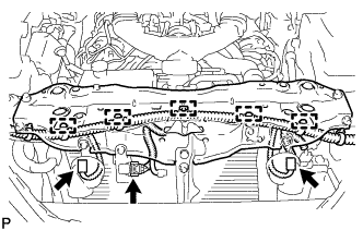
Disconnect the 3 connectors and detach the 5 wire harness clamps to disconnect the wire harness.
-
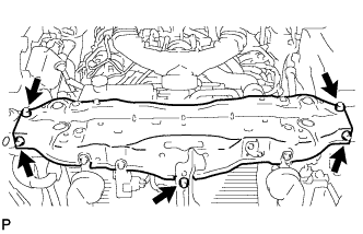
Remove the 5 bolts and radiator upper support.
-
-
DISCONNECT DISCHARGE HOSE SUB-ASSEMBLY
-
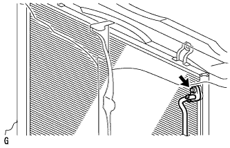
Remove the bolt and disconnect the discharge hose sub-assembly from the cooler condenser assembly.
Note
-
When loosening the bolt, do not allow any tools to contact the hose.
-
When loosening the bolt, hold a part of the hose near the connector.
-
-
Remove the O-ring from the discharge hose sub-assembly.
Note
Seal the openings of the disconnected parts using vinyl tape to prevent moisture and foreign matter from entering them.
-
-
DISCONNECT LIQUID TUBE SUB-ASSEMBLY A
-
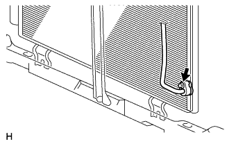
Remove the bolt and disconnect the liquid tube sub-assembly A from the cooler condenser.
Note
-
When loosening the bolt, do not allow any tools to contact the tube.
-
When loosening the bolt, hold a part of the tube near the connector.
-
-
Remove the O-ring from the liquid tube sub-assembly A.
Note
Seal the openings of the disconnected parts using vinyl tape to prevent moisture and foreign matter from entering them.
-
-
REMOVE COOLER CONDENSER ASSEMBLY
-
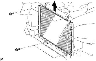
Remove the 4 bolts and cooler condenser assembly.
-
-
REMOVE COOLER DRYER
-
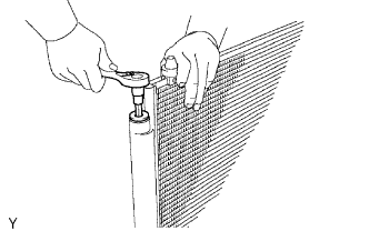
Using a 14 mm socket hexagon wrench, remove the cap from the modulator.
-
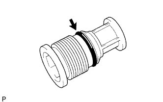
Remove the O-ring from the cap.
-
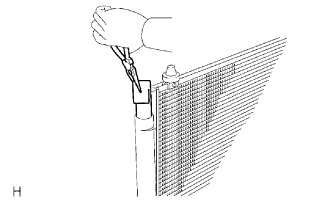
Using pliers, remove the cooler dryer.
-