COMPRESSOR (for AWD) INSTALLATION

-
ADJUST COMPRESSOR OIL
-
When replacing the compressor and magnetic clutch with a new one, gradually discharge the refrigerant gas from the service valve, and drain the following amount of oil from the new compressor and magnetic clutch before installation.
Standard (Oil capacity inside the new compressor and magnetic clutch: 130 + 15 cc (4.6 + 0.51 fl. oz.)) - (Remaining oil amount in the removed compressor and magnetic clutch) = (Oil amount to be removed from the new compressor when replacing) Note
-
When checking the compressor oil level, observe the A/C system's precautions.
-
If a new compressor and magnetic clutch is installed without removing some oil remaining in the pipes of the vehicle, the oil amount will be too large. This prevents heat exchange in the refrigerant cycle and causes refrigerant failure.
-
If the volume of oil remaining in the removed compressor and magnetic clutch is too small, check for oil leakage.
-
Be sure to use ND-OIL 8 or equivalent for compressor oil.
-
-
-
INSTALL WITH PULLEY COMPRESSOR ASSEMBLY
-
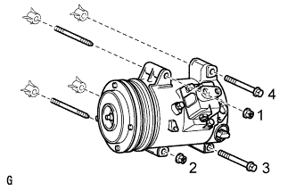
Using an E8 "TORX" socket wrench, install the with pulley compressor assembly with the 2 stud bolts.
- Torque:
- 10 N*m { 102 kgf*cm, 7 ft.*lbf }
-
Install the 2 bolts and 2 nuts.
- Torque:
- 25 N*m { 250 kgf*cm, 18 ft.*lbf }
Note
Tighten the nuts and bolts in the order shown in the illustration to install the with pulley compressor.
-
Connect the connector.
-
-
INSTALL EXHAUST MANIFOLD SUB-ASSEMBLY LH
-
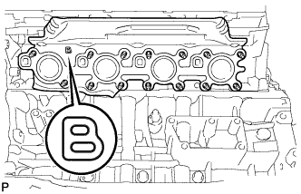
Place a new gasket on the cylinder head with the "B" mark facing the manifold side.
Note
Make sure that the gasket is installed facing the proper direction.
-
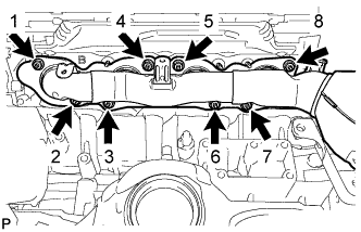
Install the exhaust manifold with the new nuts by uniformly tightening the nuts in several steps, in the sequence shown in the illustration.
- Torque:
- 21 N*m { 214 kgf*cm, 15 ft.*lbf }
-
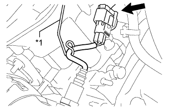
Text in Illustration *1 Bracket Connect the air fuel ratio sensor connector.
-
Hook the wire harness to the bracket.
-
-
INSTALL NO. 2 EXHAUST MANIFOLD HEAT INSULATOR
-
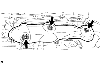
Install the heat insulator with the 3 bolts.
- Torque:
- 10 N*m { 102 kgf*cm, 7 ft.*lbf }
-
-
INSTALL ENGINE AND TRANSMISSION