COMPRESSOR (for 2WD) REMOVAL

-
RECOVER REFRIGERANT FROM REFRIGERATION SYSTEM
- SST
- 09985-20010 ( 09985-02130, 09985-02150, 09985-02090, 09985-02110, 09985-02010, 09985-02050, 09985-02060, 09985-02070 )
-
Start the engine.
-
Turn the A/C switch ON.
-
Operate the cooler compressor with an engine speed of approximately 1,000 rpm for 5 to 6 minutes to circulate the refrigerant and collect the compressor oil remaining in each component into the cooler compressor.
-
Stop the engine.
-
Recover the refrigerant from the A/C system using a refrigerant recovery unit.
-
REMOVE COWL TOP VENTILATOR LOUVER
-

for LHD:
Remove the 6 clips and cowl top ventilator louver RH.
-

for RHD:
Remove the 6 clips and cowl top ventilator louver LH.
-
-
PRECAUTION
Note
After turning the engine switch off, waiting time may be required before disconnecting the cable from the battery terminal. Therefore, make sure to read the disconnecting the cable from the battery terminal notice before proceeding with work Click here.
-
DISCONNECT CABLE FROM NEGATIVE BATTERY TERMINAL
Note
When disconnecting the cable, some systems need to be initialized after the cable is reconnected Click here.
-
REMOVE EXHAUST MANIFOLD SUB-ASSEMBLY LH
for 1UR-FE: Click here
for 1UR-FSE: Click here
-
DISCONNECT SUCTION TUBE SUB-ASSEMBLY B
-
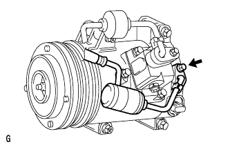
Remove the bolt and disconnect the suction tube sub-assembly B from the with pulley compressor assembly.
-
Remove the O-ring from the cooler refrigerant suction tube sub-assembly B.
Note
Seal the openings of the disconnected parts using vinyl tape to prevent moisture and foreign matter from entering them.
-
-
DISCONNECT DISCHARGE HOSE SUB-ASSEMBLY
-
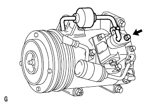
Remove the bolt and disconnect the discharge hose sub-assembly from the with pulley compressor assembly.
-
Remove the O-ring from the discharge hose sub-assembly.
Note
Seal the openings of the disconnected parts using vinyl tape to prevent moisture and foreign matter from entering them.
-
-
REMOVE WITH PULLEY COMPRESSOR ASSEMBLY
-
Disconnect the connector.
-
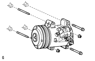
Remove the 2 bolts and 2 nuts.
-
Using an E8 "TORX" socket wrench, remove the 2 stud bolts and with pulley compressor assembly.
-