AIR CONDITIONING SYSTEM Smoke Sensor Circuit
DESCRIPTION
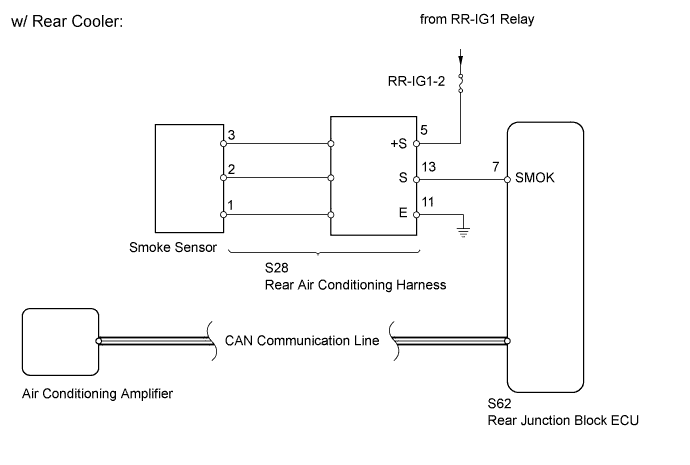
This sensor detects the smoke level inside the cabin and sends the appropriate signals to the rear junction block ECU.
Tech Tips
This circuit uses the CAN communication line. Before performing the inspection, check that the CAN communication system is functioning normally.
WIRING DIAGRAM
INSPECTION PROCEDURE
PROCEDURE
-
INSPECT FUSE (RR-IG1-2)
-
Remove the RR-IG1-2 fuse from the luggage room junction block.
-
Measure the resistance of the fuse.
Standard resistance Tester Connection Condition Specified Condition RR-IG1-2 fuse Always Below 1 Ω
NG 
REPLACE FUSE
OK 
-
-
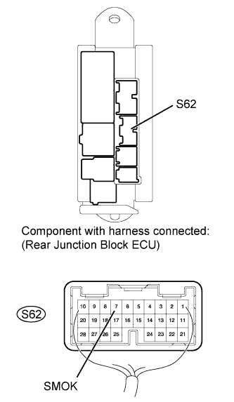
CHECK REAR JUNCTION BLOCK ECU (SMOK VOLTAGE)
-
Remove the rear junction block ECU with connectors still connected.
-
Measure the voltage according to the value(s) in the table below when applying or not applying cigarette smoke.
Standard voltage Tester Connection Switch Condition Specified Condition S62-7 (SMOK) - Body ground Engine switch on (IG)
Rear cooler AUTO switch ON
Apply cigarette smoke
Above 4.0 V Engine switch on (IG)
Rear cooler AUTO switch ON
No cigarette smoke
Below 1 V
NG 
INSPECT SMOKE SENSOR Click here
OK 
PROCEED TO NEXT CIRCUIT INSPECTION SHOWN IN PROBLEM SYMPTOMS TABLE Click here
-
-
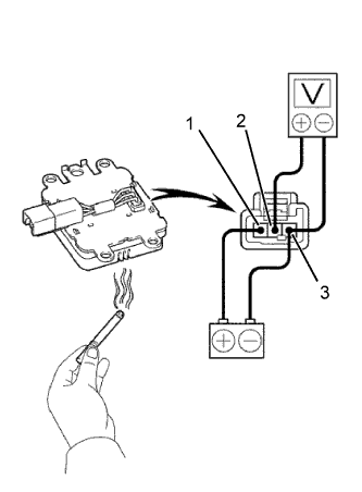
INSPECT SMOKE SENSOR
-
Remove the smoke sensor Click here.
-
Connect the positive (+) lead from the battery to terminal 1 and negative (-) lead to terminal 3.
-
Measure the voltage according to the value(s) in the table below.
Standard voltage Tester Connection Condition Specified Condition 2 - 3 There is no cigarette smoke Below 1.0 V There is cigarette smoke Above 4.0 V Note
Since the sensor determines the amount of smoke based on the changes in the amount of light, check the sensor in an area with as little ambient light as possible.
NG
REPLACE SMOKE SENSOR Click here
OK
-
-
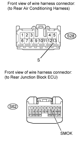
CHECK HARNESS AND CONNECTOR (REAR JUNCTION BLOCK ECU - REAR AIR CONDITIONING HARNESS)
-
Disconnect the S62 rear junction block ECU connector.
-
Disconnect the S28 rear air conditioning harness connector.
-
Measure the resistance according to the value(s) in the table below.
Standard resistance Tester Connection Condition Specified Condition S62-7 (SMOK) - S28-13 (S) Always Below 1 Ω S62-7 (SMOK) - Body ground Always 10 kΩ or higher
NG
REPAIR OR REPLACE HARNESS OR CONNECTOR
OK
-
-
CHECK REAR AIR CONDITIONING HARNESS
Tech Tips
Replace the rear air conditioning harness with a normal one and check that the condition returns to normal Click here.
OK Same problem does not occur.
NG
REPLACE REAR JUNCTION BLOCK ECU
OK
END (REAR AIR CONDITIONING HARNESS IS DEFECTIVE)