AIR CONDITIONING UNIT (for Front Side) INSTALLATION

Tech Tips
-
Use the same procedure for RHD and LHD vehicles.
-
The procedure listed below is for LHD vehicles.
-
A bolt without a torque specification is shown in the standard bolt chart Click here.
-
INSTALL AIR CONDITIONING UNIT ASSEMBLY
-
Install the air conditioning unit with the nut.
- Torque:
- 9.8 N*m { 100 kgf*cm, 87 in.*lbf }
-
-
INSTALL INSTRUMENT PANEL REINFORCEMENT ASSEMBLY
-
Install the instrument panel reinforcement with the No. 1 instrument panel spacer.
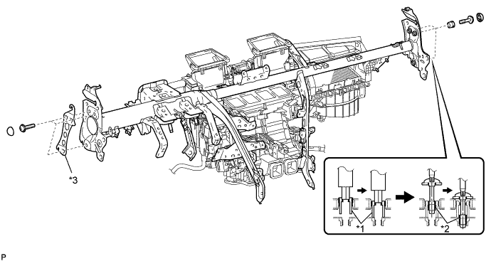
Text in Illustration *1 Collar *2 "TORX" Bolt *3 No. 1 Instrument Panel Spacer - - -
Passenger side:
Using a 12 mm hexagon wrench, tighten the 3 collars.
-
Using a T40 "TORX" socket, install the 6 "TORX" bolts.
- Torque:
- 20 N*m { 204 kgf*cm, 15 ft.*lbf }
-
Install the 6 instrument panel safety pad caps.
-
Install the 9 bolts and 2 screws.
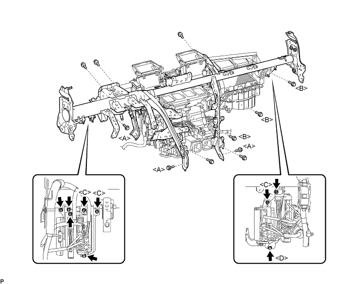
- Torque:
- for Bolt A
- 20 N*m { 204 kgf*cm, 15 ft.*lbf }
- for Bolt B
- 9.8 N*m { 100 kgf*cm, 87 in.*lbf }
-
Connect the ground wires and install the junction block with the bolts and nuts.
- Torque:
- for Nut C
- 8.0 N*m { 82 kgf*cm, 71 in.*lbf }
- for Bolt D
- 13 N*m { 127 kgf*cm, 9 ft.*lbf }
-
Attach the clamps and connectors and install the wire harness.
-
-
INSTALL WINDSHIELD WIPER MOTOR ASSEMBLY
-
CONNECT COOLER UNIT DRAIN HOSE
-
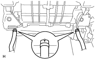
Connect the 2 cooler unit drain hoses as shown in the illustration.
-
-
INSTALL STEERING COLUMN ASSEMBLY
w/o VGRS: Click here
for 2WD with VGRS: Click here
for AWD with VGRS; Click here
-
INSTALL NO. 1 AIR DUCT SUB-ASSEMBLY
-
Attach the 2 claws to install the No. 1 air duct sub-assembly.
-
Install the bolt.
- Torque:
- 9.8 N*m { 100 kgf*cm, 87 in.*lbf }
-
-
INSTALL NO. 2 AIR DUCT SUB-ASSEMBLY
-
Attach the 2 claws to install the No. 2 air duct sub-assembly.
-
Install the screw.
-
-
INSTALL INSTRUMENT PANEL SAFETY PAD SUB-ASSEMBLY
-
CONNECT HEATER WATER OUTLET HOSE
-
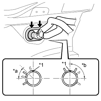
Text in Illustration *1 Paint Mark *a 30° to 60° *b 75° to 105° Connect the heater water outlet hose and attach the clip.
Tech Tips
Perform the installation with the hose clip and mark at the correct angle.
-
-
CONNECT HEATER WATER INLET HOSE
Tech Tips
Use the same procedure described for the water outlet hose.
-
CONNECT COOLER REFRIGERANT LIQUID PIPE A
-
Remove the attached vinyl tape from the pipe.
-
Sufficiently apply compressor oil to a new O-ring and the fitting surface of the cooler refrigerant liquid pipe A.
Compressor oil ND-OIL 8 or equivalent -
Install the O-ring to the cooler refrigerant liquid pipe A.
-
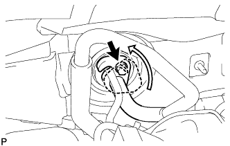
Connect the cooler refrigerant liquid pipe A.
-
Turn the hook connector in the direction indicated by the arrow in the illustration.
-
Install the bolt.
- Torque:
- 9.8 N*m { 100 kgf*cm, 7 ft.*lbf }
-
-
CONNECT SUCTION TUBE SUB-ASSEMBLY B
-
Remove the attached vinyl tape from the tube.
-
Sufficiently apply compressor oil to a new O-ring and the fitting surface of the suction tube sub-assembly B.
Compressor oil ND-OIL 8 or equivalent -
Install the O-ring to the suction tube sub-assembly B.
-
Connect the suction tube sub-assembly B.
-
Turn the hook connector in the direction indicated by the arrow in the illustration.
-
Install the bolt.
- Torque:
- 9.8 N*m { 100 kgf*cm, 7 ft.*lbf }
-
-
CONNECT CABLE TO NEGATIVE BATTERY TERMINAL
Note
When disconnecting the cable, some systems need to be initialized after the cable is reconnected Click here.
-
INSTALL COWL TOP VENTILATOR LOUVER
-

for LHD:
Install the 6 clips and cowl top ventilator louver RH.
Note
If the cowl top ventilator louver RH is not properly installed, water may leak into the engine room and cause malfunctions. Therefore, make sure the cowl top ventilator louver RH is installed properly.
-

for RHD:
Install the 6 clips and cowl top ventilator louver LH.
Note
If the cowl top ventilator louver LH is not properly installed, water may leak into the engine room and cause malfunctions. Therefore, make sure the cowl top ventilator louver LH is installed properly.
-
-
ADD ENGINE COOLANT
for 1UR-FE: Click here
for 1UR-FSE: Click here
-
ADD COMPRESSOR OIL
-
When performing work on air conditioning parts, follow the oil guidelines below in order to protect the cooler compressor.
Part and Condition Oil Level (cc) Work Procedure Compressor replacement -100 to -120 Drain oil from new compressor Condenser replacement 35 to 55 Fill oil into replacement part Evaporator replacement 40 to 60 A/C pipe replacement High pressure 5 to 25 Low pressure When discharging refrigerant gas quickly 30 to 50 While applying vacuum, use manifold gauge to fill oil from low pressure side valve
-
-
CHARGE REFRIGERANT
- SST
- 09985-20010 ( 09985-02130, 09985-02150, 09985-02090, 09985-02110, 09985-02010, 09985-02050, 09985-02060, 09985-02070 )
-
Perform vacuum purging using a vacuum pump.
-
Charge refrigerant HFC-134a (R134a).
Standard Destination Air Conditioning Type Refrigerant Charging Amount except G.C.C Countries w/o Rear Cooler 550 +/-50 g (19.4 +/-1.8 oz.) w/ Rear Cooler 700 +/-30 g (24.7 +/-1.1 oz.) G.C.C Countries w/o Rear Cooler 750 +/-30 g (26.5 +/-1.1 oz.) w/ Rear Cooler 1000 +/-50 g (35.3 +/-1.8 oz.) 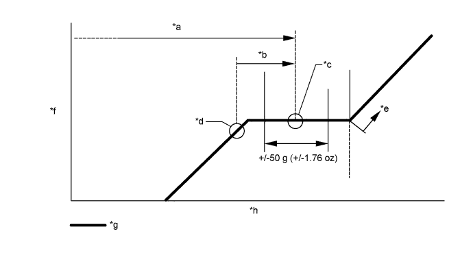
Text in Illustration *a Amount to be charged *b Charge 100 g (3.53 oz) *c Mean value in proper range *d Point where bubbles disappear *e Overcharged *f Pressure *g Sub-cool system *h Refrigerant amount Note
-
Do not operate the cooler compressor before charging refrigerant as the cooler compressor will not work properly without any refrigerant, and will overheat.
-
Approximately 200 g (7.05 oz.) of refrigerant may need to be charged after bubbles disappear. The refrigerant amount should be checked by measuring its quantity, and not with the sight glass.
-
-
WARM UP ENGINE
-
Warm up the engine at less than 1850 rpm for 2 minutes or more after charging the refrigerant.
Note
Be sure to warm up the compressor when turning the A/C switch ON after removing and installing the cooler refrigerant lines (including the compressor) to prevent damage to the compressor.
-
-
INSPECT FOR ENGINE COOLANT LEAK
CAUTION:
Do not remove the radiator reservoir cap while the engine and radiator are still hot. Pressurized, hot engine coolant and steam may be released and cause serious burns.
Note
Before each inspection, turn the A/C switch OFF.
-
Fill the radiator with coolant and attach a radiator cap tester.
-
Warm up the engine.
-
Using the radiator cap tester, increase the pressure inside the radiator to 118 kPa (1.2 kgf/cm2, 17 psi), and check that the pressure does not drop.
If the pressure drops, check the hoses, radiator and water pump for leaks. If no external leaks are found, check the heater core, cylinder block and head.
-
-
CHECK FOR LEAKAGE OF REFRIGERANT
-
After recharging the refrigerant gas, check for refrigerant gas leakage using a halogen leak detector.
-
Perform the operation under these conditions:
-
Stop the engine.
-
Secure good ventilation (the halogen leak detector may react to volatile gases other than refrigerant, such as evaporated gasoline or exhaust gas).
-
Repeat the test 2 or 3 times.
-
Make sure that some refrigerant remains in the refrigeration system.
Tech Tips
When compressor is off:
approximately 392 to 588 kPa (4 to 6 kgf/cm2, 57 to 85 psi)
-
-
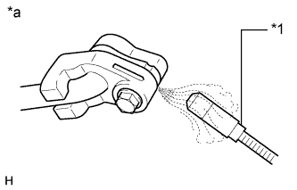
Text in Illustration *1 Halogen Leak Detector *a Check for Leakage Using a halogen leak detector, check the refrigerant line for leakage.
-
If a gas leak is not detected on the drain hose, remove the blower motor control (blower resistor) from the cooling unit. Insert the halogen leak detector sensor into the unit and perform the test.
-
Disconnect the connector and wait for approximately 20 minutes. Bring the halogen leak detector close to the pressure switch and perform the test.
-
-
CHECK SRS WARNING LIGHT