AIR CONDITIONING UNIT (for Front Side) DISASSEMBLY

-
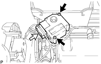
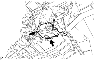
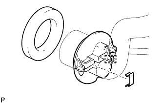
REMOVE BLOWER ASSEMBLY
-
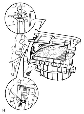
Remove the screw.
-
Disconnect the connector.
-
Detach the claw and remove the blower assembly.
-
-
REMOVE NO. 1 AIR DUCT SUB-ASSEMBLY
-
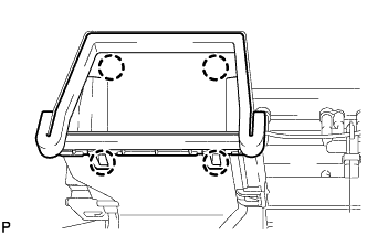
Detach the 4 claws and remove the No. 1 air duct sub-assembly.
-
-
REMOVE NO. 2 AIR DUCT SUB-ASSEMBLY
-
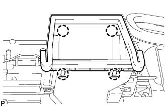
Detach the 4 claws and remove the No. 2 air duct sub-assembly.
-
-
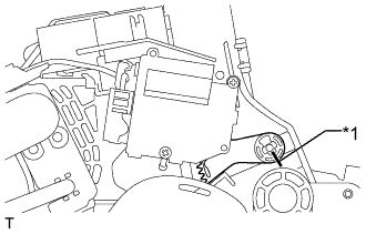
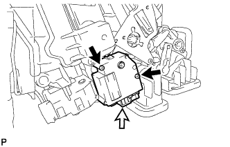
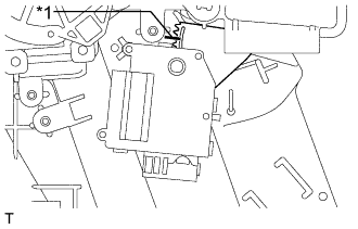
REMOVE COOL AIR BYPASS SERVO MOTOR LH
-
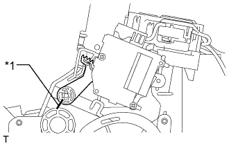
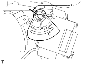
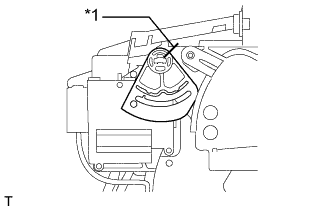
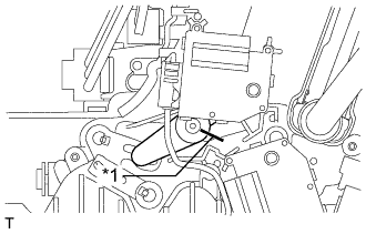
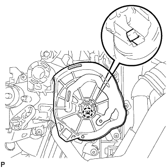
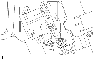
When reusing the cool air bypass servo motor LH:
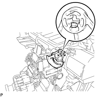
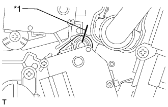
Place alignment marks on the moving parts and air conditioning unit as shown in the illustration.
Text in Illustration *1 Alignment Marks -
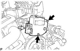
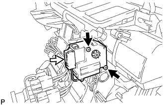
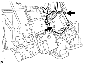
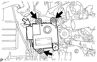
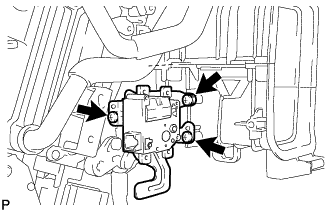
Disconnect the connector.
-
Remove the 2 screws and cool air bypass servo motor LH.
-
-
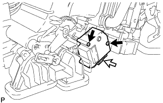
REMOVE COOL AIR BYPASS SERVO MOTOR RH
-
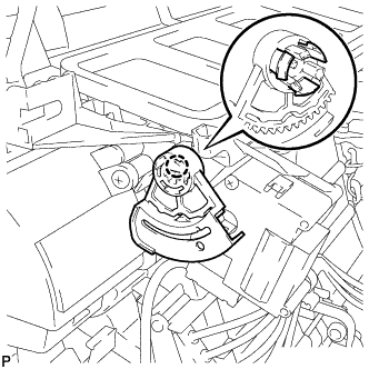
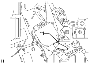
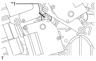
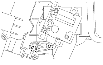
When reusing the cool air bypass servo motor RH:
Place alignment marks on the moving parts and air conditioning unit as shown in the illustration.
Text in Illustration *1 Alignment Marks -
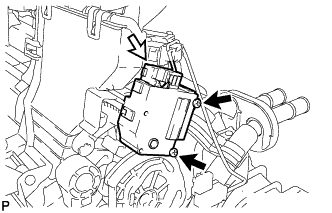
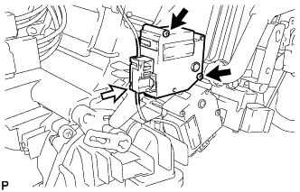
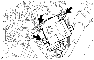
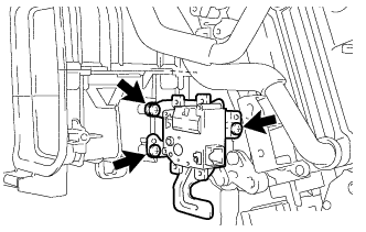
Disconnect the connector.
-
Remove the 2 screws and cool air bypass servo motor RH.
-
-
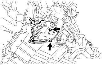
REMOVE AIR MIX SERVO MOTOR LH (Cool)
-
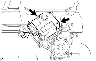
Disconnect the connector.
-
Remove the 2 screws and air mix servo motor LH (cool).
-
-
REMOVE AIR MIX SERVO MOTOR RH (Cool)
-
Disconnect the connector.
-
Remove the 2 screws and air mix servo motor RH (cool).
-
-
REMOVE AIR OUTLET SERVO MOTOR LH (Face)
-
When reusing the air outlet servo motor LH (Face):
Place alignment marks on the moving parts and air conditioning unit as shown in the illustration.
Text in Illustration *1 Alignment Marks -
Detach the 3 claws and remove the lever.
-
Disconnect the connector.
-
Remove the 2 screws and air outlet servo motor LH (Face).
-
-
REMOVE AIR OUTLET SERVO MOTOR RH (Face)
-
When reusing the air outlet servo motor RH (Face):
Place alignment marks on the moving parts and air conditioning unit as shown in the illustration.
Text in Illustration *1 Alignment Marks -
Detach the claw and remove the lever.
-
Disconnect the connector.
-
Remove the 2 screws and air outlet servo motor RH (Face).
-
-
REMOVE AIR OUTLET SERVO MOTOR LH (Front A/C Rear Air Flow)
-
When reusing the air outlet servo motor LH (front A/C rear air flow):
Place alignment marks on the moving parts and air conditioning unit as shown in the illustration.
Text in Illustration *1 Alignment Marks -
Disconnect the connector.
-
Remove the 2 screws and air outlet servo motor LH (front A/C rear air flow).
-
-
REMOVE AIR OUTLET SERVO MOTOR RH (Front A/C Rear Air Flow) (for 4 Zone Type)
-
When reusing the air outlet servo motor RH (front A/C rear air flow):
Place alignment marks on the moving parts and air conditioning unit as shown in the illustration.
Text in Illustration *1 Alignment Marks -
Disconnect the connector.
-
Remove the 2 screws and air outlet servo motor RH (front A/C rear air flow).
-
-
REMOVE AIR MIX SERVO MOTOR LH (Front A/C Rear Air Flow) (for 4 Zone Type)
-
When reusing the air mix servo motor LH (front A/C rear air flow):
Place alignment marks on the moving parts and air conditioning unit as shown in the illustration.
Text in Illustration *1 Alignment Marks -
Disconnect the connector.
-
Remove the 2 screws and air mix servo motor LH (front A/C rear air flow).
-
-
REMOVE AIR MIX SERVO MOTOR RH (Front A/C Rear Air Flow)
-
When reusing the air mix servo motor RH (front A/C Rear Air Flow):
Place alignment marks on the moving parts and air conditioning unit as shown in the illustration.
Text in Illustration *1 Alignment Marks -
Disconnect the connector.
-
Remove the 2 screws and air mix servo motor RH (front A/C Rear Air Flow).
-
-
REMOVE AIR MIX SERVO MOTOR LH (Hot)
-
Disconnect the connector.
-
Remove the 2 screws and air mix servo motor LH (Hot).
-
-
REMOVE AIR MIX SERVO MOTOR RH (Hot)
-
Disconnect the connector.
-
Remove the 2 screws and air mix servo motor RH (Hot).
-
-
REMOVE MAX HOT BYPASS SERVO MOTOR (Hot)
-
When reusing the max hot air bypass servo motor (hot):
Place alignment marks on the moving parts and air conditioning unit as shown in the illustration.
Text in Illustration *1 Alignment Marks -
Disconnect the connector.
-
Remove the 2 screws and max hot air bypass servo motor (hot).
-
-
REMOVE AIR OUTLET SERVO MOTOR LH (Foot/Def)
-
Detach the claw and remove the main plate.
-
Disconnect the connector.
-
Remove the 3 screws and air outlet servo motor LH (foot/def).
-
-
REMOVE AIR OUTLET SERVO MOTOR RH (Foot/Def)
-
Detach the claw and remove the main plate.
-
Disconnect the connector.
-
Remove the 3 screws and air outlet servo motor RH (foot/Def).
-
-
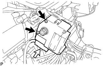
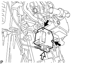
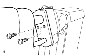
REMOVE QUICK HEATER ASSEMBLY (w/ PTC Heater)
-
Remove the 3 screws and bracket.
-
Remove the 2 screws.
-
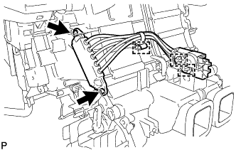
Detach the 2 connector clamps and harness clamp and remove the quick heater assembly.
-
-
REMOVE AIR CONDITIONER HARNESS ASSEMBLY
-
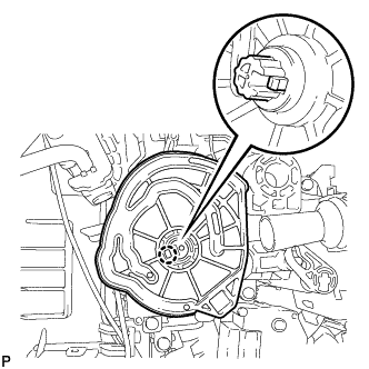
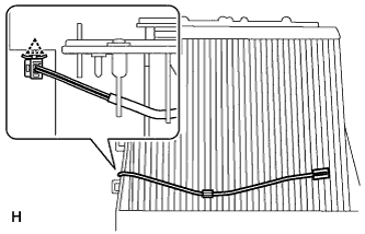
REMOVE HEATER RADIATOR UNIT SUB-ASSEMBLY
-
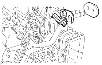
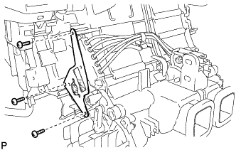
Remove the packing.
-
Remove the screw and clamp.
-
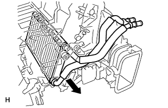
Remove the heater radiator unit sub-assembly as shown in the illustration.
-
-
REMOVE NO. 1 COOLER EVAPORATOR SUB-ASSEMBLY
-
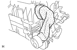
Remove the No. 2 cooling unit packing and No. 3 cooling unit packing from the air conditioner assembly.
-
Remove the packing from the bracket.
-
Remove the holding spring and detach the hook, and then remove the bracket from the air conditioner tube assembly.
-
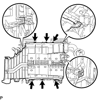
Remove the 6 screws.
-
Detach the 3 claws and remove the front cooling unit case (back side).
-
Remove the No. 1 cooler evaporator sub-assembly.
-
-
REMOVE NO. 1 COOLER THERMISTOR
-
Detach the clamp and remove the No. 1 cooler thermistor.
-
-
REMOVE COOLER EXPANSION VALVE
-
Using a 4 mm hexagon wrench, remove the 2 hexagon bolts and air conditioner tube assembly.
-
Remove the 2 O-rings from the air conditioner tube assembly.
-
Remove the cooler expansion valve from the evaporator.
-
Remove the 2 O-rings from the evaporator.
-
-
REMOVE MAX HOT BYPASS SERVO MOTOR (Cool) (for LHD)
-
Detach the claw and remove the lever.
-
Remove the 3 screws and max hot bypass servo motor (cool).
-
-
REMOVE MAX HOT BYPASS SERVO MOTOR (Cool) (for RHD)
-
Detach the claw and remove the lever.
-
Remove the 3 screws and max hot bypass servo motor (cool).
-