AIR CONDITIONING SYSTEM, Diagnostic DTC:B1419/19

| DTC Code | DTC Name |
|---|---|
| B1419/19 | Rear Room Temperature Sensor Circuit |
DESCRIPTION
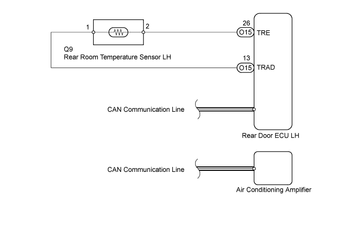
The rear room temperature sensor LH is installed in the rear door trim board LH to detect the rear room temperature and control the heater and air conditioner "AUTO" mode. The resistance of the rear room temperature sensor changes in accordance with the rear room temperature for LH seat. As the temperature decreases, the resistance increases. As the temperature increases, the resistance decreases.
The rear door ECU LH sends the read signal to the air conditioning amplifier via the CAN communication line. The rear door ECU LH applies voltage (5 V) to the rear room temperature sensor and reads voltage changes as the resistance of the rear room temperature sensor changes. This sensor also sends the appropriate signals to the rear door ECU LH.
Tech Tips
This circuit uses the CAN communication line. Before performing the inspection, check that the CAN communication system is functioning normally.
| DTC No. | DTC Detection Condition | Trouble Area |
|---|---|---|
| B1419/19 | Open or short in rear room temperature sensor LH circuit |
|
WIRING DIAGRAM
INSPECTION PROCEDURE
PROCEDURE
-
READ VALUE USING INTELLIGENT TESTER (REAR ROOM TEMPERATURE SENSOR)
-
Use the Data List to check if the rear room temperature sensor for LH seat is functioning properly.
Air Conditioner Tester Display Measurement Item / Range Normal Condition Diagnostic Note Room Temperature Sensor (Rear) Rear room temperature sensor for LH seat/
Min.: -6.5°C (20.3°F)
Max.: 57.25°C (135.05°F)
Actual rear room temperature for LH seat is displayed Open in circuit: -6.5°C (20.3°F)
Short in circuit: 57.25°C (135.05°F)
OK The display is as specified in the normal condition. Result Result Proceed to NG A OK (Checking from the PROBLEM SYMPTOMS TABLE) B OK (Checking from the DTC) C
B 
PROCEED TO NEXT CIRCUIT INSPECTION SHOWN IN PROBLEM SYMPTOMS TABLE Click here
C
REPLACE AIR CONDITIONING AMPLIFIER Click here
A 
-
-
INSPECT REAR ROOM TEMPERATURE SENSOR LH
-
Remove the rear room temperature sensor LH Click here.
-
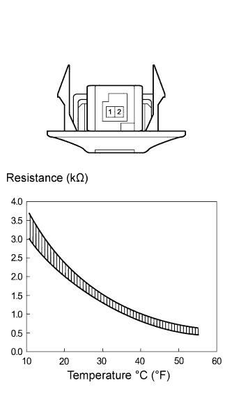
Measure the resistance according to the value(s) in the table below.
Standard resistance Tester Connection Condition Specified Condition 1 - 2 10°C (50°F) 3.00 to 3.73 kΩ 1 - 2 15°C (59°F) 2.45 to 2.88 kΩ 1 - 2 20°C (68°F) 1.95 to 2.30 kΩ 1 - 2 25°C (77°F) 1.60 to 1.80 kΩ 1 - 2 30°C (86°F) 1.28 to 1.47 kΩ 1 - 2 35°C (95°F) 1.00 to 1.22 kΩ 1 - 2 40°C (104°F) 0.80 to 1.00 kΩ 1 - 2 45°C (113°F) 0.65 to 0.85 kΩ 1 - 2 50°C (122°F) 0.50 to 0.70 kΩ 1 - 2 55°C (131°F) 0.44 to 0.60 kΩ 1 - 2 60°C (140°F) 0.36 to 0.50 kΩ Note
Even slightly touching the sensor may change the resistance value. Be sure to hold the connector of the sensor.
Tech Tips
As the temperature increases, the resistance decreases (see the graph).
NG
REPLACE REAR ROOM TEMPERATURE SENSOR LH Click here
OK
-
-
CHECK HARNESS AND CONNECTOR (REAR ROOM TEMPERATURE SENSOR LH - REAR DOOR ECU LH)
-
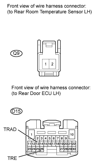
Disconnect the Q9 rear room temperature sensor LH connector.
-
Disconnect the O15 rear door ECU LH connector.
-
Measure the resistance according to the value(s) in the table below.
Standard resistance Tester Connection Condition Specified Condition Q9-2 - O15-26 (TRE) Always Below 1 Ω Q9-1 - O15-13 (TRAD) Always Below 1 Ω O15-26 (TRE) - Body ground Always 10 kΩ or higher O15-13 (TRAD) - Body ground Always 10 kΩ or higher
NG
REPAIR OR REPLACE HARNESS OR CONNECTOR
OK 
REPLACE REAR DOOR ECU LH
-