STEERING GEAR (for 2WD with VGRS) REMOVAL

-
PLACE FRONT WHEELS FACING STRAIGHT AHEAD
-
REMOVE COWL TOP VENTILATOR LOUVER
-

for LHD:
Remove the 6 clips and cowl top ventilator louver RH.
-

for RHD:
Remove the 6 clips and cowl top ventilator louver LH.
-
-
PRECAUTION
Note
After turning the engine switch off, waiting time may be required before disconnecting the cable from the negative (-) battery terminal. Therefore, make sure to read the disconnecting the cable from the negative (-) battery terminal notices before proceeding with work Click here.
-
DISCONNECT CABLE FROM NEGATIVE BATTERY TERMINAL
Note
When disconnecting the cable, some systems need to be initialized after the cable is reconnected Click here.
-
REMOVE FRONT WHEELS
-
REMOVE NO. 1 ENGINE UNDER COVER
-
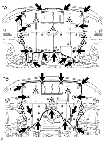
Text in Illustration *A for 2WD *B for AWD Remove the 13 screws, 7 clips and No. 1 engine under cover.
-
-
REMOVE FRONT SUSPENSION MEMBER PROTECTOR LOWER
-
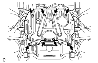
Remove the 8 bolts and front suspension member protector lower.
-
-
REMOVE NO. 2 ENGINE UNDER COVER
-
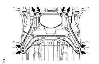
Remove the 8 bolts and No. 2 engine under cover.
-
-
DISCONNECT STEERING SLIDING WITH SHAFT YOKE SUB-ASSEMBLY
-
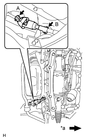
Text in Illustration *a Front of the vehicle Loosen bolt A and remove bolt B, then slide the steering sliding with shaft yoke.
Note
-
Do not remove bolt A.
-
Do not separate the steering sliding with shaft yoke from the power steering link.
-
-
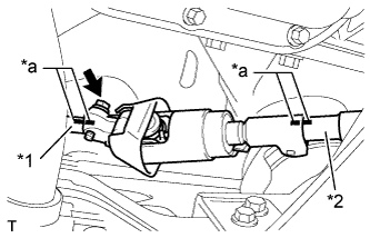
Text in Illustration *1 No. 2 steering intermediate shaft *2 Power steering link *a Matchmark Put matchmarks on the steering sliding with shaft yoke, No. 2 steering intermediate shaft and power steering link.
-
Remove the bolt and the steering sliding with shaft yoke from the power steering link.
-
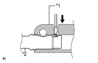
Text in Illustration *1 Steering sliding with shaft yoke *2 No. 2 steering intermediate shaft Separate the steering sliding with shaft yoke from the No. 2 steering intermediate shaft.
Tech Tips
Insert a screwdriver or equivalent into the yoke's hole. Hold down the intermediate shaft's claw and remove the No. 2 steering intermediate shaft. If the claw is damaged, remove the claw. The intermediate shaft does not have to be replaced.
-
-
DISCONNECT TIE ROD ASSEMBLY LH
-
Remove the clip and nut.
-
Install 2 spacers (SST spacer B) onto the tie rod assembly LH so that there is a space of approximately 1 mm (0.0397 in.) between the arm and spacers.
- SST
- 09960-20010 ( 09961-02060 )
Note
-
Make sure to install the spacers (SST spacer B) as the steering knuckle spacer may shift.
-
As SST may become damaged, make sure the space between the arm and spacers is not 1 mm (0.0397 in.) or less.
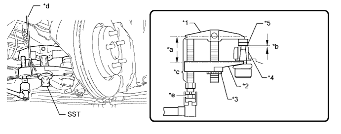
Text in Illustration *1 Body *2 Claw *3 Nut *4 Spacer B *a Parallel *b 1 mm (0.0397 in.) *c Molybdenum Grease Application Area *d String *e Place the wrench here - - Note
-
Do not damage the dust cover.
-
As the dust cover may be damaged, adjust SST with the center nut so that the body and crow are the parallel.
-
Make sure to tie the string of SST to the vehicle to prevent SST from dropping.
-
Using SST, disconnect the tie rod assembly from the steering knuckle.
- SST
- 09960-20010 ( 09961-02010 )
-
-
DISCONNECT TIE ROD ASSEMBLY RH
Tech Tips
Use the same procedures described for the LH side.
-
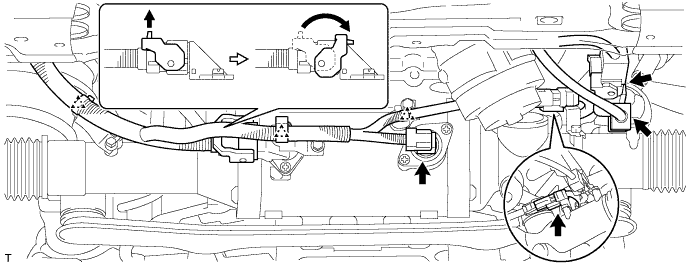
REMOVE POWER STEERING LINK ASSEMBLY
-
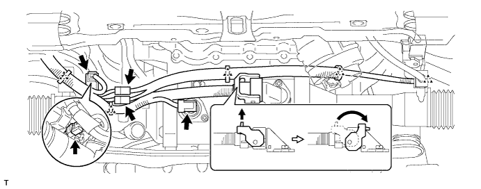
for LHD:
Detach the 3 clips and disconnect the 5 connectors.
-
for RHD:
Detach the 5 clips and disconnect the 5 connectors.
-
Remove the 4 bolts, 4 nuts and power steering link from the front frame and rack housing bracket.
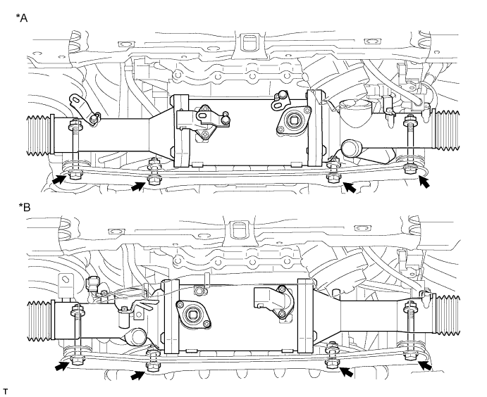
Text in Illustration *A for LHD *B for RHD
-