POWER STEERING SYSTEM PS Warning Light Remains ON
DESCRIPTION
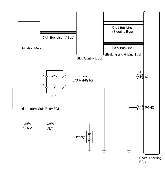
The power steering ECU is connected to the combination meter via CAN communication. If any of the following are detected, the PS warning light remains on.
-
The power steering ECU connectors are disconnected from the power steering ECU.
-
There is a malfunction in the power steering ECU internal circuit.
-
There is an open in the harness between the combination meter and power steering ECU.
WIRING DIAGRAM
INSPECTION PROCEDURE
PROCEDURE
-
INSPECT FUSE (E/G RM-IG1-2)
-
Remove the E/G RM-IG1-2 fuse from the engine room No. 2 relay block.
-
Measure the resistance of the fuse.
Standard resistance Tester Connection Condition Specified Condition E/G RM-IG1-2 fuse Always Below 1 Ω
NG 
REPLACE FUSE
OK 
-
-
CHECK HARNESS AND CONNECTOR
-
Start the engine.
-
Check the indication condition of the PS warning light by wiggling the power steering ECU connector and wire harness up and down, and right and left.
OK PS warning light indication condition does not change.
NG
REPAIR OR REPLACE HARNESS OR CONNECTOR
OK
-
-
CHECK CAN COMMUNICATION SYSTEM
-
Using the intelligent tester, check for DTCs and confirm that there are no problems in the CAN communication system Click here (for LHD) and Click here (for RHD)).
Result DTC Condition Proceed to DTC is not output A DTC is output (for LHD) B DTC is output (for RHD) C
B
GO TO CAN COMMUNICATION SYSTEM (for LHD) Click here
C
GO TO CAN COMMUNICATION SYSTEM (for RHD) Click here
A
-
-
CHECK BRAKE CONTROL SYSTEM
-
Using the intelligent tester, check for DTCs and confirm that there are no problems in the brake control system.
Result DTC Condition Proceed to DTC is not output A DTC is output B
B
GO TO BRAKE CONTROL SYSTEM Click here
A
-
-
CHECK HARNESS AND CONNECTOR (POWER STEERING ECU - BODY GROUND)
-
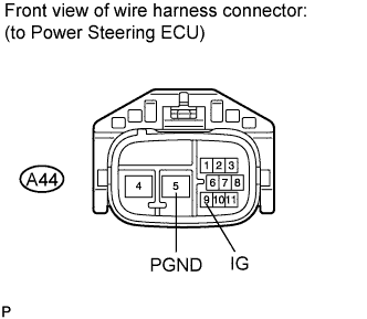
Disconnect the A44 ECU connector.
-
Measure the voltage according to the value(s) in the table below.
Standard voltage Tester Connection Switch Condition Specified Condition A44-9 (IG) - Body ground Engine switch on (IG) 11 to 14 V -
Measure the resistance according to the value(s) in the table below.
Standard resistance Tester Connection Condition Specified Condition A44-5 (PGND) - Body ground Always Below 1 Ω
NG
REPAIR OR REPLACE HARNESS OR CONNECTOR
OK
-
-
REPLACE POWER STEERING ECU
-
Replace the power steering ECU Click here.
-
After replacing the power steering ECU, check the illumination condition of the combination meter's PS warning light.
OK Engine switch turned on (IG), illuminated → engine started, turns off. Note
If replacing the power steering ECU, initialize the rotation angle sensor value and calibrate the torque sensor zero point Click here.
NG
REPLACE NO. 1 METER ECU SUB-ASSEMBLY Click here
OK 
END
-