POWER STEERING SYSTEM, Diagnostic DTC:C1555

| DTC Code | DTC Name |
|---|---|
| C1555 | Motor Relay Welding Failure |
DESCRIPTION
The power steering ECU supplies current to the power steering motor.
| DTC Code | DTC Detection Condition | Trouble Area |
|---|---|---|
| C1555 | Motor relay malfunction is detected. |
|
Tech Tips
If there are any tears or holes in the rack boots, water or other foreign material may enter the interior of the power steering link assembly and cause a malfunction.
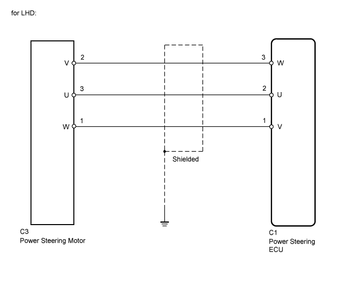
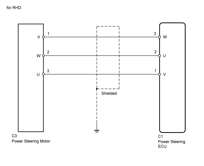
WIRING DIAGRAM
INSPECTION PROCEDURE
PROCEDURE
-
CHECK CONNECTORS
-
Check the connection of the power steering ECU and power steering link assembly connectors.
-
Visually inspect the terminals of the power steering ECU and power steering link assembly connectors.
Result Result Proceed to Normal A Connectors not properly connected B Power steering ECU connector terminals abnormal C Power steering link assembly connector terminals abnormal (w/ VGRS) D Power steering link assembly connector terminals abnormal (w/o VGRS) E Note
-
If replacing the power steering link assembly, clear the rotation angle sensor value calibration value, initialize the rotation angle sensor value, and calibrate the torque sensor zero point Click here.
-
If replacing the power steering ECU, initialize the rotation angle sensor value and calibrate the torque sensor zero point Click here.
-
B 
CONNECT CONNECTORS CORRECTLY
C
REPLACE POWER STEERING ECU Click here
D
REPLACE POWER STEERING LINK ASSEMBLY (w/ VGRS) Click here
E
REPLACE POWER STEERING LINK ASSEMBLY (w/o VGRS) Click here
A 
-
-
CHECK HARNESS AND CONNECTOR (POWER STEERING ECU - POWER STEERING MOTOR)
-
Disconnect the C1 ECU connector.
-
Disconnect the C3 motor connector.
-
Measure the resistance according to the value(s) in the table below.
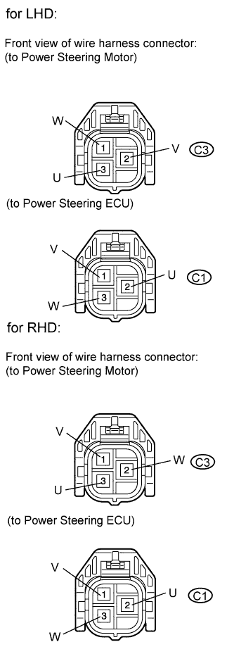
Standard resistance (for LHD) Tester Connection Condition Specified Condition C1-1 (V) - C3-1 (W) Always Below 1 Ω C1-2 (U) - C3-3 (U) Always Below 1 Ω C1-3 (W) - C3-2 (V) Always Below 1 Ω C1-1 (V) - Body ground Always 10 kΩ or higher C1-2 (U) - Body ground Always 10 kΩ or higher C1-3 (W) - Body ground Always 10 kΩ or higher Standard resistance (for RHD) Tester Connection Condition Specified Condition C1-1 (V) - C3-3 (U) Always Below 1 Ω C1-2 (U) - C3-2 (W) Always Below 1 Ω C1-3 (W) - C3-1 (V) Always Below 1 Ω C1-1 (V) - Body ground Always 10 kΩ or higher C1-2 (U) - Body ground Always 10 kΩ or higher C1-3 (W) - Body ground Always 10 kΩ or higher
NG
REPAIR OR REPLACE HARNESS OR CONNECTOR
OK
-
-
INSPECT POWER STEERING LINK ASSEMBLY (POWER STEERING MOTOR)
-
Disconnect the C3 motor connector.
-
Measure the resistance according to the value(s) in the table below.
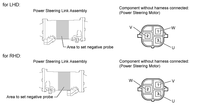
Standard resistance (for LHD) Tester Connection Condition Specified Condition 3 (U) - 2 (V) Always 0.07 to 10 Ω 2 (V) - 1 (W) Always 0.07 to 10 Ω 1 (W) - 3 (U) Always 0.07 to 10 Ω 3 (U) - Body ground* Always 100 kΩ or higher 2 (V) - Body ground* Always 100 kΩ or higher 1 (W) - Body ground* Always 100 kΩ or higher Standard resistance (for RHD) Tester Connection Condition Specified Condition 3 (U) - 2 (W) Always 0.07 to 10 Ω 2 (W) - 1 (V) Always 0.07 to 10 Ω 1 (V) - 3 (U) Always 0.07 to 10 Ω 3 (U) - Body ground* Always 100 kΩ or higher 2 (W) - Body ground* Always 100 kΩ or higher 1 (V) - Body ground* Always 100 kΩ or higher *: Touch the negative probe to the power steering link assembly housing at the position shown in the illustration to perform the measurement.
Note
-
If replacing the power steering link assembly, clear the rotation angle sensor value calibration value, initialize the rotation angle sensor value, and calibrate the torque sensor zero point Click here.
-
If replacing the power steering ECU, initialize the rotation angle sensor value and calibrate the torque sensor zero point Click here.
Result Result Proceed to OK A NG (w/ VGRS) B NG (w/o VGRS) C -
B
REPLACE POWER STEERING LINK ASSEMBLY (w/ VGRS) Click here
C
REPLACE POWER STEERING LINK ASSEMBLY (w/o VGRS) Click here
A
-
-
CHECK POWER STEERING LINK ASSEMBLY (CHECK RACK BOOTS FOR LEAK)
-
Remove the power steering link assembly.
-
w/ VGRS Click here
-
w/o VGRS Click here
-
-
Clean off any dirt or foreign matter attached to the rack boots.
-
Rotate the pinion shaft all the way to the end, and with the rack boot extended, check to make sure there are no holes. Use this procedure to check both the LH and RH boots.
OK There are no tears or holes. Note
-
If replacing the power steering link assembly, clear the rotation angle sensor value calibration value, initialize the rotation angle sensor value, and calibrate the torque sensor zero point Click here.
-
If replacing the power steering ECU, initialize the rotation angle sensor value and calibrate the torque sensor zero point Click here.
Result Result Proceed to OK A NG (w/ VGRS) B NG (w/o VGRS) C -
B
REPLACE POWER STEERING LINK ASSEMBLY (w/ VGRS) Click here
C
REPLACE POWER STEERING LINK ASSEMBLY (w/o VGRS) Click here
A 
REPLACE POWER STEERING ECU Click here
-