STEERING GEAR (for 2WD with VGRS) INSTALLATION

-
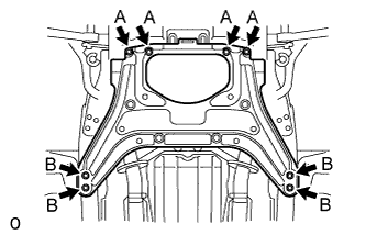
INSTALL POWER STEERING LINK ASSEMBLY
-
Install the power steering link and rack housing bracket to the front frame with the 4 bolts and 4 nuts.
- Torque:
- 70 N*m { 714 kgf*cm, 52 ft.*lbf }
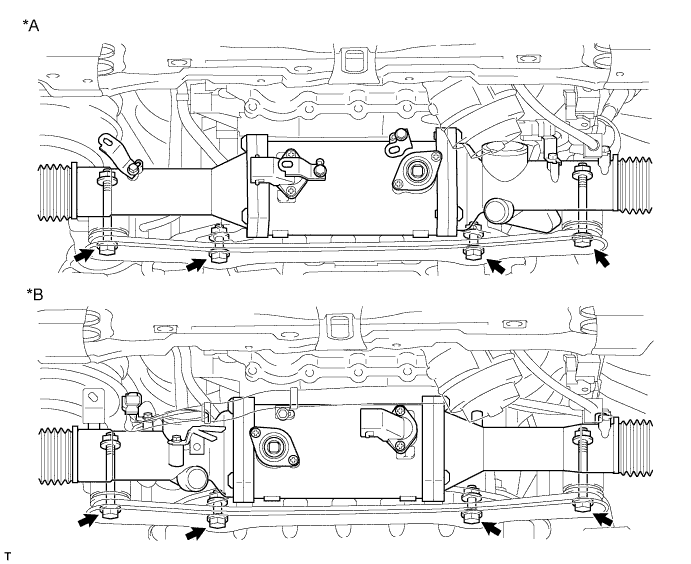
Text in Illustration *A for LHD *B for RHD -
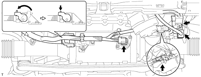
for LHD:
Connect the 5 connectors and attach the 3 clips.
-
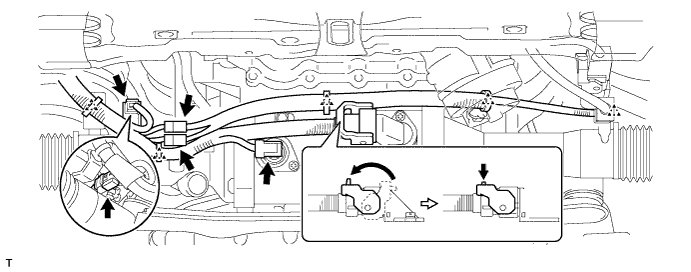
for RHD:
Connect the 5 connectors and attach the 5 clips.
-
-
CONNECT TIE ROD ASSEMBLY LH
-
Connect the tie rod LH to the steering knuckle with the nut.
- Torque:
- 60 N*m { 612 kgf*cm, 44 ft.*lbf }
-
Install a new clip.
-
-
CONNECT TIE ROD ASSEMBLY RH
Tech Tips
Use the same procedures described for the LH side.
-
CONNECT STEERING SLIDING WITH SHAFT YOKE SUB-ASSEMBLY
-
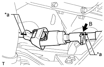
Text in Illustration *a Matchmark Align the matchmarks on the No. 2 steering intermediate shaft assembly and steering sliding with shaft yoke.
-
Align the matchmarks on the steering sliding with shaft yoke and power steering link.
-
Temporarily install bolt B.
Note
Do not tighten the bolt.
-
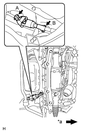
Text in Illustration *a Front of the vehicle Install bolt A and tighten bolt B.
- Torque:
- 35 N*m { 360 kgf*cm, 26 ft.*lbf }
-
-
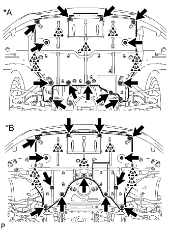
INSTALL NO. 2 ENGINE UNDER COVER
-
Install the No. 2 engine under cover with the 8 bolts.
- Torque:
- for Bolt A
- 10 N*m { 102 kgf*cm, 7 ft.*lbf }
- for Bolt B
- 27 N*m { 275 kgf*cm, 20 ft.*lbf }
-
-
INSTALL FRONT SUSPENSION MEMBER PROTECTOR LOWER
-
Install the front suspension lower crossmember with the 4 bolts.
- Torque:
- 25 N*m { 255 kgf*cm, 18 ft.*lbf }
-
Install the 2 clips.
-
-
INSTALL NO. 1 ENGINE UNDER COVER
-
Text in Illustration *A for 2WD *B for AWD Remove the 13 screws, 7 clips and No. 1 engine under cover.
-
-
INSTALL FRONT WHEELS
- Torque:
- 140 N*m { 1428 kgf*cm, 103 ft.*lbf }
-
CONNECT CABLE TO NEGATIVE BATTERY TERMINAL
-
INSTALL COWL TOP VENTILATOR LOUVER
-

for LHD:
Install the 6 clips and cowl top ventilator louver RH.
Note
If the cowl top ventilator louver RH is not properly installed, water may leak into the engine room and cause malfunctions. Therefore, make sure the cowl top ventilator louver RH is installed properly.
-

for RHD:
Install the 6 clips and cowl top ventilator louver LH.
Note
If the cowl top ventilator louver LH is not properly installed, water may leak into the engine room and cause malfunctions. Therefore, make sure the cowl top ventilator louver LH is installed properly.
-
-
PLACE FRONT WHEELS FACING STRAIGHT AHEAD
-
PERFORM INITIALIZATION
Note
When disconnecting the cable, some systems need to be initialized after the cable is reconnected Click here.
-
CHECK SUSPENSION CONTROL SYSTEM
-
INSPECT AND ADJUST FRONT WHEEL ALIGNMENT
-
ADJUST HEADLIGHT AIMING
-
ADJUST OBJECT RECOGNITION CAMERA
-
CHECK SRS WARNING LIGHT
-
INITIALIZE ROTATION ANGLE SENSOR AND CALIBRATE TORQUE SENSOR ZERO POINT
-
PERFORM VARIABLE GEAR RATIO STEERING SYSTEM CALIBRATION