STEERING CONTROL ECU INSTALLATION

Tech Tips
-
Use the same procedures for the RHD and LHD.
-
The procedures listed below are for the LHD.
-
INSTALL STEERING CONTROL ECU
-
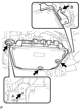
Install the ECU with the 3 screws.
- Torque:
- 5.5 N*m { 56 kgf*cm, 49 in.*lbf }
Tech Tips
-
Align positioning boss A of the blower with the hole of the ECU.
-
Securely attach the hook B of the ECU to the blower.
-
Connect the 3 ECU connectors.
-
-
INSTALL NO. 2 INSTRUMENT PANEL UNDER COVER SUB-ASSEMBLY
-
Connect the connector.
-
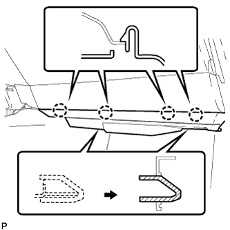
Insert the 2 guides.
-
Attach the 4 claws to install the No. 2 instrument panel under cover sub-assembly.
-
-
CONNECT CABLE TO NEGATIVE BATTERY TERMINAL
-
INSTALL COWL TOP VENTILATOR LOUVER
-

for LHD:
Install the 6 clips and cowl top ventilator louver RH.
Note
If the cowl top ventilator louver RH is not properly installed, water may leak into the engine room and cause malfunctions. Therefore, make sure the cowl top ventilator louver RH is installed properly.
-

for RHD:
Install the 6 clips and cowl top ventilator louver LH.
Note
If the cowl top ventilator louver LH is not properly installed, water may leak into the engine room and cause malfunctions. Therefore, make sure the cowl top ventilator louver LH is installed properly.
-
-
CHECK SRS WARNING LIGHT
-
PERFORM INITIALIZATION
Note
When disconnecting the cable, some systems need to be initialized after the cable is reconnected Click here.
-
PERFORM VARIABLE GEAR RATIO STEERING SYSTEM CALIBRATION