POWER STEERING SYSTEM, Diagnostic DTC:C1521, C1522, C1523, C1524, C1532

| DTC Code | DTC Name |
|---|---|
| C1521 | Motor Circuit Malfunction |
| C1522 | Motor Circuit Malfunction |
| C1523 | Motor Circuit Malfunction |
| C1524 | Motor Circuit Malfunction |
| C1532 | ECU Malfunction |
DESCRIPTION
The power steering ECU supplies current to the power steering motor through this circuit.
| DTC No. | DTC Detection Condition | Trouble Area |
|---|---|---|
| C1521 | Motor overcurrent |
|
| C1522 | Motor current sensor malfunction |
|
| C1523 | Excessively large current deviation |
|
| C1524 | Voltage error between motor terminals |
|
| C1532 | ECU internal malfunction (Peripheral circuit malfunction) is detected |
|
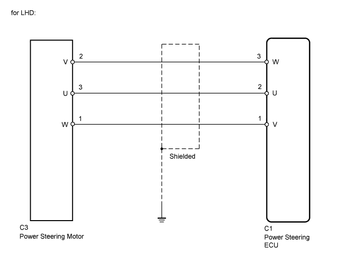
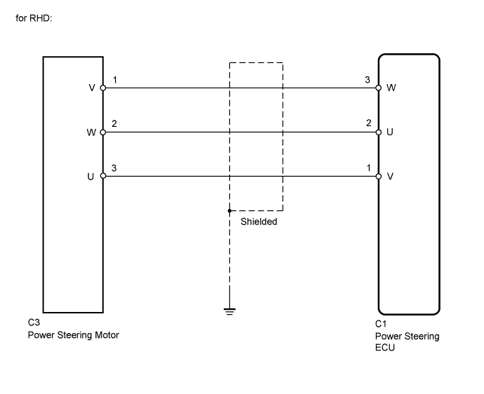
WIRING DIAGRAM
INSPECTION PROCEDURE
PROCEDURE
-
RECONFIRM DTC
-
Check for DTCs Click here.
Result DTC Condition Proceed to Only DTC C1521, C1522, C1523, C1524 or C1532 is output A DTC C1555 is output together with other DTCs B Tech Tips
If DTC C1555 is output, perform troubleshooting for C1555 first.
B 
GO TO DIAGNOSTIC TROUBLE CODE CHART Click here
A 
-
-
CHECK CONNECTORS
-
Check the connection of the power steering ECU and power steering link assembly connectors.
-
Visually inspect the terminals of the power steering ECU and power steering link assembly connectors.
Result Result Proceed to Normal A Connectors not properly connected B Power steering ECU connector terminals abnormal C Power steering link assembly connector terminals abnormal (w/ VGRS) D Power steering link assembly connector terminals abnormal (w/o VGRS) E Note
-
If replacing the power steering link assembly, clear the rotation angle sensor value calibration value, initialize the rotation angle sensor value, and calibrate the torque sensor zero point Click here.
-
If replacing the power steering ECU, initialize the rotation angle sensor value and calibrate the torque sensor zero point Click here.
-
B
CONNECT CONNECTORS CORRECTLY
C
REPLACE POWER STEERING ECU Click here
D
REPLACE POWER STEERING LINK ASSEMBLY (w/ VGRS) Click here
E
REPLACE POWER STEERING LINK ASSEMBLY (w/o VGRS) Click here
A
-
-
CHECK HARNESS AND CONNECTOR (POWER STEERING ECU - POWER STEERING MOTOR)
-
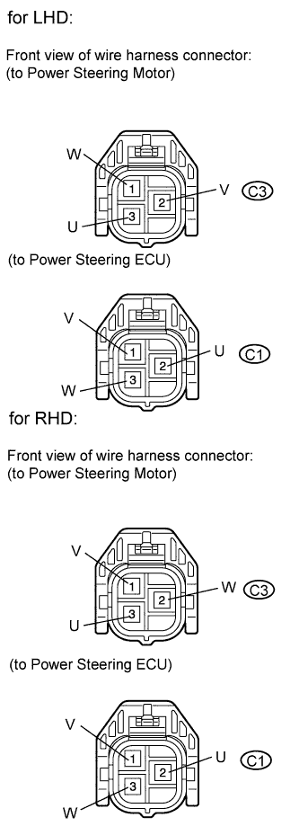
Disconnect the C1 ECU connector.
-
Disconnect the C3 motor connector.
-
Measure the resistance according to the value(s) in the table below.
Standard resistance (for LHD) Tester Connection Condition Specified Condition C1-1 (V) - C3-1 (W) Always Below 1 Ω C1-2 (U) - C3-3 (U) Always Below 1 Ω C1-3 (W) - C3-2 (V) Always Below 1 Ω C1-1 (V) - Body ground Always 10 kΩ or higher C1-2 (U) - Body ground Always 10 kΩ or higher C1-3 (W) - Body ground Always 10 kΩ or higher Standard resistance (for RHD) Tester Connection Condition Specified Condition C1-1 (V) - C3-3 (U) Always Below 1 Ω C1-2 (U) - C3-2 (W) Always Below 1 Ω C1-3 (W) - C3-1 (V) Always Below 1 Ω C1-1 (V) - Body ground Always 10 kΩ or higher C1-2 (U) - Body ground Always 10 kΩ or higher C1-3 (W) - Body ground Always 10 kΩ or higher
NG
REPAIR OR REPLACE HARNESS OR CONNECTOR
OK
-
-
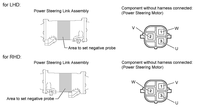
INSPECT POWER STEERING LINK ASSEMBLY (POWER STEERING MOTOR)
-
Disconnect the C3 motor connector.
-
Measure the resistance according to the value(s) in the table below.
Standard resistance (for LHD) Tester Connection Condition Specified Condition 3 (U) - 2 (V) Always 0.07 to 10 Ω 2 (V) - 1 (W) Always 0.07 to 10 Ω 1 (W) - 3 (U) Always 0.07 to 10 Ω 3 (U) - Body ground* Always 100 kΩ or higher 2 (V) - Body ground* Always 100 kΩ or higher 1 (W) - Body ground* Always 100 kΩ or higher Standard resistance (for RHD) Tester Connection Condition Specified Condition 3 (U) - 2 (W) Always 0.07 to 10 Ω 2 (W) - 1 (V) Always 0.07 to 10 Ω 1 (V) - 3 (U) Always 0.07 to 10 Ω 3 (U) - Body ground* Always 100 kΩ or higher 2 (W) - Body ground* Always 100 kΩ or higher 1 (V) - Body ground* Always 100 kΩ or higher *: Touch the negative probe to the power steering link assembly housing at the position shown in the illustration to perform the measurement.
Note
-
If replacing the power steering link assembly, clear the rotation angle sensor value calibration value, initialize the rotation angle sensor value, and calibrate the torque sensor zero point Click here.
-
If replacing the power steering ECU, initialize the rotation angle sensor value and calibrate the torque sensor zero point Click here.
Result Result Proceed to OK A NG (w/ VGRS) B NG (w/o VGRS) C -
B
REPLACE POWER STEERING LINK ASSEMBLY (w/ VGRS) Click here
C
REPLACE POWER STEERING LINK ASSEMBLY (w/o VGRS) Click here
A 
REPLACE POWER STEERING ECU Click here
-