HEATED STEERING WHEEL SYSTEM TERMINALS OF ECU

-
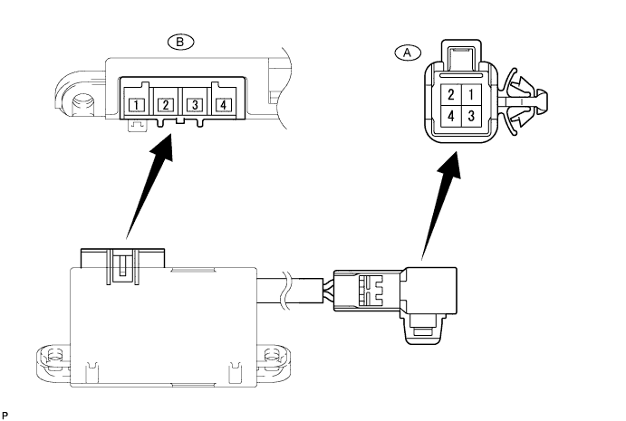
CHECK HEATED STEERING WHEEL CONTROLLER
Tech Tips
Inspect the connectors from the back side while the connectors are connected.
-
Measure the voltage or resistance according to the value(s) in the table below.
Terminal No. (Symbol) Terminal Description Condition Specified Condition A-1 (CCU) - Body ground LED output signal Engine switch on (IG)
Steering heater switch on
Below 3 V A-2 (CCV) - Body ground Steering heater switch input signal Engine switch on (IG)
Steering heater switch pressed and held
11 to 14 V A-3 (CCX) - Body ground Ground Always Below 1 Ω A-4 (CCW) - Body ground IG power supply Engine switch on (IG) 11 to 14 V B-1 (TH1) - Body ground Thermistor input signal Engine switch on (IG) 1.5 to 4.5 V*1 B-2 (TH2) - Body ground Thermistor ground Engine switch on (IG)
Steering heater switch on
Below 1 V B-3 (SH2) - Body ground Heater output signal Engine switch on (IG)
Steering heater switch on
11 to 14 V*2 B-4 (SH1) - Body ground Heater ground Engine switch on (IG)
Steering heater switch on
Below 1 V Tech Tips
-
*1: When ambient temperature is 0 to 40°C (32 to 104°F).
-
*2: The current to the heater turns ON/OFF depending on the temperature of the thermistor. As a result, it may take several minutes before a voltage value is output.
-
-
-
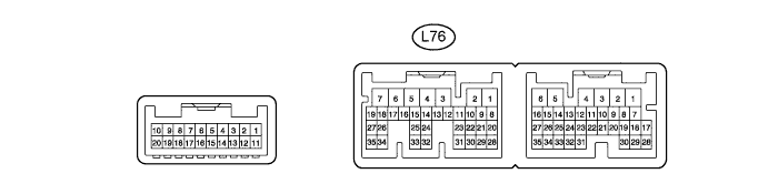
CHECK AIR CONDITIONING AMPLIFIER
-
Measure the voltage and resistance according to the value(s) in the table below.
Tech Tips
Check from the rear of the connector while it is connected to the air conditioning amplifier.
Terminal No.
(Symbol)
Terminal Description Condition Specified Condition L76-9 (SHOT) - L76-1 (GND) Heated steering heater LED operation output signal Engine switch on (IG)
Outer mirror switch (Heated steering wheel switch) off
11 to 14 V Engine switch on (IG)
Outer mirror switch (Heated steering wheel switch) on
Below 1 Ω L76-30 (SHSI) - L76-1 (GND) Heated steering heater switch input signal Engine switch on (IG)
Outer mirror switch (Heated steering wheel switch) off
4.75 to 5.25 V Engine switch on (IG)
Outer mirror switch (Heated steering wheel switch) on
Below 1 Ω L76-31 (SHIN) - L76-1 (GND) Heated steering heater condition output signal Engine switch on (IG)
Outer mirror switch (Heated steering wheel switch) off
4.75 to 5.25 V Engine switch on (IG)
Outer mirror switch (Heated steering wheel switch) on
Below 1 Ω L76-34 (SHSO) - L76-1 (GND) Heated steering heater drive command output signal Engine switch on (IG)
Outer mirror switch (Heated steering wheel switch) off
Below 1 Ω Engine switch on (IG)
Outer mirror switch (Heated steering wheel switch) on
11 to 14 V
-