VARIABLE GEAR RATIO STEERING SYSTEM, Diagnostic DTC:C1595/55, C15C4/68

| DTC Code | DTC Name |
|---|---|
| C1595/55 | Lost Communication with Steering Angle Sensor Module |
| C15C4/68 | Steering Angle Signal (Test Mode DTC) |
DESCRIPTION
Signal transmission between the steering control ECU and steering angle sensor is performed via serial communication.
If an error occurs between them in the serial communication, the ECU will store DTC C1595/55.
| DTC Code | Detection Condition | Trouble Area |
|---|---|---|
| C1595/55 | The steering control ECU detects an error in serial communication between the ECU and steering angle sensor |
|
| C15C4/68 | A steering signal indicating a tire angle of 36° or more (to the left or right) is input after transfer to test mode* |
|
Tech Tips
*: A tire angle of 36° and a motor rotation angle of 36° correspond to the steering wheel angle. The amount of change in tire angle and motor rotation angle is from when the mode is changed to test mode.
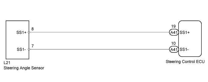
WIRING DIAGRAM
INSPECTION PROCEDURE
Note
When replacing the steering angle sensor, confirm that the replacement part is of the correct specification.
PROCEDURE
-
CHECK DTC (CAN COMMUNICATION SYSTEM)
-
Check for DTCs in the CAN communication system Click here for LHD, Click here for RHD).
Result Result Proceed to DTC is not output A DTC is output LHD B RHD C
B 
GO TO CAN COMMUNICATION SYSTEM (DIAGNOSTIC TROUBLE CODE CHART) Click here
C
GO TO CAN COMMUNICATION SYSTEM (DIAGNOSTIC TROUBLE CODE CHART) Click here
A 
-
-
CHECK STEERING ANGLE SENSOR
-
Check if a steering angle sensor that complies with the vehicle specifications is installed.
OK A steering angle sensor that complies with the vehicle specifications is installed.
NG
REPLACE STEERING ANGLE SENSOR Click here
OK
-
-
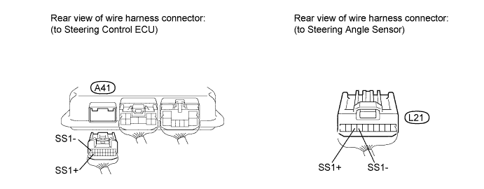
CHECK HARNESS AND CONNECTOR (STEERING CONTROL ECU - STEERING ANGLE SENSOR)
-
Disconnect the A41 steering control ECU connector.
-
Disconnect the L21 steering angle sensor connector.
-
Measure the resistance according to the value(s) in the table below.
Standard resistance Tester Connection Condition Specified Condition A41-10 (SS1-) - L21-7 (SS1-) Always Below 1 Ω A41-19 (SS1+) - L21-8 (SS1+) Always Below 1 Ω A41-19 (SS1+) - Body ground Always 10 kΩ or higher A41-10 (SS1-) - Body ground Always 10 kΩ or higher A41-19 (SS1+) - A41-10 (SS1-) Always 10 kΩ or higher
NG
REPAIR OR REPLACE HARNESS OR CONNECTOR
OK
-
-
CHECK STEERING ANGLE SENSOR
-
Disconnect the A41 steering control ECU connector.
Tech Tips
The resistance must be measured after the steering angle sensor connector is connected.
-
Adjust the shift lever to neutral.
-
Jack up the vehicle.
-
Turn the engine switch on (IG).
-
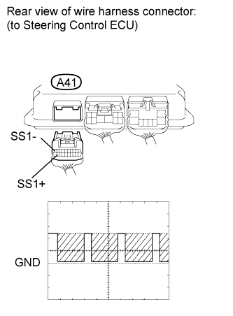
Check the waveform of the steering angle sensor using an oscilloscope.
Standard voltage Tester Connection Switch Condition Specified Condition A41-19 (SS1+) -
A41-10 (SS1-)
Engine switch on (IG), rotate steering wheel slowly Pulse generation
(0 to 5 V)
Tech Tips
The output voltage should fluctuate up and down similarly to the diagram when the wheel is turned slowly.
NG
REPLACE STEERING ANGLE SENSOR Click here
OK 
REPLACE STEERING CONTROL ECU Click here
-