STEERING COLUMN ASSEMBLY (for AWD with VGRS) INSTALLATION

-
INSTALL STEERING COLUMN ASSEMBLY (TILT STEERING GEAR ASSEMBLY WITH MOTOR)
-
Install the steering column with the 4 nuts.
- Torque:
- 26 N*m { 260 kgf*cm, 19 ft.*lbf }
-
Connect the connectors and wire harness clamps to the steering column.
-
-
INSTALL NO. 2 STEERING INTERMEDIATE SHAFT ASSEMBLY
-
Install the clamp to the steering column hole cover sub-assembly.
-
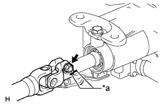
Text in Illustration *a Matchmark Align the matchmarks on the No. 2 steering intermediate shaft assembly and steering column.
-
Install the bolt.
- Torque:
- 35 N*m { 360 kgf*cm, 26 ft.*lbf }
-
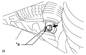
Text in Illustration *a Matchmark Align the matchmarks on the No. 2 steering intermediate shaft assembly and power steering link.
-
Install the bolt.
- Torque:
- 35 N*m { 360 kgf*cm, 26 ft.*lbf }
-
-
PLACE FRONT WHEELS FACING STRAIGHT AHEAD
-
INSTALL NO. 1 AIR DUCT SUB-ASSEMBLY
-
Attach the 2 claws to install the air duct.
-
Install the bolt.
- Torque:
- 9.8 N*m { 100 kgf*cm, 87 in.*lbf }
-
Attach the 2 claws and install the wiring harness protector.
-
-
INSTALL NO. 1 LOWER INSTRUMENT PANEL AIRBAG ASSEMBLY
-
INSTALL TURN SIGNAL SWITCH ASSEMBLY WITH SPIRAL CABLE SUB-ASSEMBLY
-
Install the turn signal switch assembly with spiral cable to the steering column with the clamp.
-
Connect the connectors to the turn signal switch assembly with spiral cable.
-
-
INSTALL STEERING COLUMN COVER (w/o Driver Monitor Camera)
-
Attach the claw to install the steering column cover upper.
-
Attach the 4 clips to install the steering column cover upper onto the instrument panel cluster finish panel.
-
Attach the 2 claws to install the steering column cover lower.
Note
Do not damage the tilt and telescopic switch.
-
Install the 3 screws.
-
-
INSTALL STEERING COLUMN COVER (w/ Driver Monitor Camera)
-
Connect the driver monitor connector.
-
Attach the claw and install the steering column cover upper.
-
Attach the 4 clips to install the steering column cover upper onto the instrument panel cluster finish panel.
-
Attach the 2 claws to install the steering column cover lower.
Note
Do not damage the tilt and telescopic switch.
-
Install the 3 screws.
-
-
ADJUST SPIRAL CABLE SUB-ASSEMBLY
-
Visually check for defects with the spiral cable sub-assembly removed from the vehicle.
-
The defects are as follows:
-
Scratches on the spiral cable sub-assembly
-
Small cracks the spiral cable sub-assembly
-
Dents on the spiral cable sub-assembly
-
Chips on the spiral cable sub-assembly
-
Cracks or other damage to the connector
OK No defects are found. Tech Tips
If any of the defects is found, replace the spiral cable sub-assembly with a new one.
-
-
-
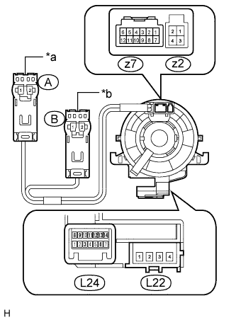
Text in Illustration *a Orange *b Black w/o Steering Heater:
Check the spiral cable sub-assembly.
Note
As the spiral cable sub-assembly may break, do not rotate the spiral cable more than the specified amount.
-
Set the spiral cable sub-assembly to the center position Click here.
-
Measure the resistance between each terminal of the spiral cable sub-assembly according to the table below.
-
After setting the spiral cable sub-assembly to the center position, rotate the spiral cable sub-assembly 2.5 times clockwise, and measure the resistance as shown. Then rotate the spiral cable sub-assembly 5 times counterclockwise, and measure the resistance as shown.
Standard resistance Tester Connection Condition Specified Condition L22-1 - B2 Always Below 1 Ω L22-2 - B1 L22-3 - A1 L22-4 - A2 L24-1 - L23-3 L24-2 - z7-7 L24-2 - L23-4 L24-3 - z7-8 L24-4 - z7-9 L24-5 - z7-10 L24-6 - z7-11 L24-7 - z7-12 L24-8 - L23-2 L24-9 - z7-1 L24-10 - z7-2 L24-11 - z7-3 L24-12 - z7-4 L24-13 - z7-5 L24-14 - z7-6 If the value is not within the specified range, replace the spiral cable sub-assembly.
-
-
w/ Steering Heater:
Check the spiral cable sub-assembly.
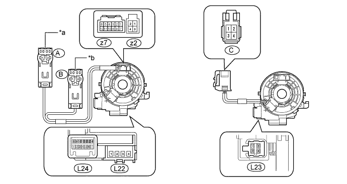
Text in Illustration *a Orange *b Black Note
As the spiral cable sub-assembly may break, do not rotate the spiral cable sub-assembly more than the specified amount.
-
Set the spiral cable sub-assembly to the center position Click here.
-
Measure the resistance between each terminal of the spiral cable sub-assembly according to the table below.
-
After setting the spiral cable sub-assembly to the center position, rotate the spiral cable sub-assembly 2.5 times clockwise, and measure the resistance as shown. Then rotate the spiral cable sub-assembly 5 times counterclockwise, and measure the resistance as shown.
Standard resistance Tester Connection Condition Specified Condition L22-1 - B2 Always Below 1 Ω L22-2 - B1 L22-3 - A1 L22-4 - A2 L24-1 - L23-3 L24-2 - z7-7 L24-2 - L23-4 L24-3 - z7-8 L24-4 - z7-9 L24-5 - z7-10 L24-6 - z7-11 L24-7 - z7-12 L24-8 - L23-2 L24-9 - z7-1 L24-10 - z7-2 L24-11 - z7-3 L24-12 - z7-4 L24-13 - z7-5 L24-14 - z7-6 C-1 - L23-1 Below 3 Ω C-2 - L23-3 C-3 - L23-2 Less than 1 Ω C-4 - L23-4 If the value is not within the specified range, replace the spiral cable sub-assembly.
-
-
-
INSTALL STEERING WHEEL ASSEMBLY
-
INSPECT STEERING WHEEL CENTER POINT
-
CONNECT CABLE TO NEGATIVE BATTERY TERMINAL
Note
Reset the AUTO TILT AWAY function setting to the previous condition by changing the customize parameter Click here.
-
INSTALL COWL TOP VENTILATOR LOUVER
-

for LHD:
Install the 6 clips and cowl top ventilator louver RH.
Note
If the cowl top ventilator louver RH is not properly installed, water may leak into the engine room and cause malfunctions. Therefore, make sure the cowl top ventilator louver RH is installed properly.
-

for RHD:
Install the 6 clips and cowl top ventilator louver LH.
Note
If the cowl top ventilator louver LH is not properly installed, water may leak into the engine room and cause malfunctions. Therefore, make sure the cowl top ventilator louver LH is installed properly.
-
-
CHECK SRS WARNING LIGHT
-
PERFORM INITIALIZATION
Note
When disconnecting the cable, some systems need to be initialized after the cable is reconnected Click here.