STEERING COLUMN ASSEMBLY (for 2WD with VGRS) INSTALLATION

Tech Tips
-
Use the same procedures for the RHD and LHD.
-
The procedures listed below are for the LHD.
-
INSTALL STEERING COLUMN ASSEMBLY (TILT STEERING GEAR ASSEMBLY WITH MOTOR)
-
Install the steering column with the 4 nuts.
- Torque:
- 26 N*m { 260 kgf*cm, 19 ft.*lbf }
-
Connect the connectors and wire harness clamps to the steering column.
-
-
INSTALL NO. 2 STEERING INTERMEDIATE SHAFT ASSEMBLY
-
Install the clamp to the steering column hole shield.
-
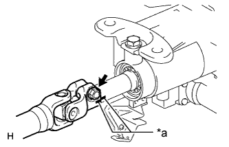
Text in Illustration *a Matchmark Align the matchmarks on the No. 2 steering intermediate shaft and steering column.
-
Install the bolt.
- Torque:
- 35 N*m { 360 kgf*cm, 26 ft.*lbf }
-
-
INSTALL STEERING SLIDING WITH SHAFT YOKE SUB-ASSEMBLY
-
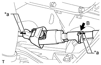
Text in Illustration *a Matchmark Align the matchmarks on the No. 2 steering intermediate shaft assembly and steering sliding with shaft yoke.
-
Align the matchmarks on the steering sliding with shaft yoke and power steering link.
-
Temporarily install bolt B.
Note
Do not tighten the bolt.
-
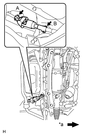
Text in Illustration *a Front of the vehicle Install bolt A and tighten bolt B.
- Torque:
- 35 N*m { 360 kgf*cm, 26 ft.*lbf }
-
-
PLACE FRONT WHEELS FACING STRAIGHT AHEAD
-
INSTALL NO. 1 AIR DUCT SUB-ASSEMBLY
-
Attach the 2 claws to install the air duct.
-
Install the bolt.
- Torque:
- 9.8 N*m { 100 kgf*cm, 87 in.*lbf }
-
Attach the 2 claws and install the wiring harness protector.
-
-
INSTALL NO. 1 LOWER INSTRUMENT PANEL AIRBAG ASSEMBLY
-
INSTALL TURN SIGNAL SWITCH ASSEMBLY WITH SPIRAL CABLE SUB-ASSEMBLY
-
Install the turn signal switch assembly with spiral cable to the steering column with the clamp.
-
Connect the connectors to the turn signal switch assembly with spiral cable.
-
-
INSTALL STEERING COLUMN COVER (w/ Driver Monitor Camera)
-
Connect the driver monitor connector.
-
Attach the claw and install the steering column cover upper.
-
Attach the 4 clips to install the steering column cover upper onto the instrument panel cluster finish panel.
-
Attach the 2 claws to install the steering column cover lower.
Note
Do not damage the tilt and telescopic switch.
-
Install the 3 screws.
-
-
INSTALL STEERING COLUMN COVER (w/o Driver Monitor Camera)
-
Attach the claw to install the steering column cover upper.
-
Attach the 4 clips to install the steering column cover upper onto the instrument panel cluster finish panel.
-
Attach the 2 claws to install the steering column cover lower.
Note
Do not damage the tilt and telescopic switch.
-
Install the 3 screws.
-
-
ADJUST SPIRAL CABLE SUB-ASSEMBLY
Note
Do not adjust the spiral cable sub-assembly with sensor with the battery connected and the engine switch on (IG).
-
Check that the engine switch is off.
-
Check that the cable is disconnected from the negative (-) battery terminal.
CAUTION:
Wait at least 90 seconds after disconnecting the cable from the negative (-) battery terminal to disable the SRS system.
-
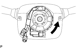
Rotate the spiral cable sub-assembly counterclockwise slowly by hand until it stops.
CAUTION:
Do not turn the spiral cable sub-assembly using the airbag wire harness.
-
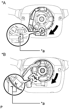
Text in Illustration *A w/o Steering Heater *B w/ Steering Heater *a Alignment Mark Rotate the spiral cable sub-assembly clockwise approximately 2.5 turns to align the marks.
CAUTION:
Do not turn the spiral cable sub-assembly using the airbag wire harness.
Tech Tips
The spiral cable sub-assembly will rotate approximately 2.5 turns to both the left and right from the center.
-
-
INSTALL STEERING WHEEL ASSEMBLY
-
INSPECT STEERING WHEEL CENTER POINT
-
CONNECT CABLE TO NEGATIVE BATTERY TERMINAL
Note
Reset the AUTO TILT AWAY function setting to the previous condition by changing the customize parameter Click here.
-
INSTALL COWL TOP VENTILATOR LOUVER
-

for LHD:
Install the 6 clips and cowl top ventilator louver RH.
Note
If the cowl top ventilator louver RH is not properly installed, water may leak into the engine room and cause malfunctions. Therefore, make sure the cowl top ventilator louver RH is installed properly.
-

for RHD:
Install the 6 clips and cowl top ventilator louver LH.
Note
If the cowl top ventilator louver LH is not properly installed, water may leak into the engine room and cause malfunctions. Therefore, make sure the cowl top ventilator louver LH is installed properly.
-
-
CHECK SRS WARNING LIGHT
-
PERFORM INITIALIZATION
Note
When disconnecting the cable, some systems need to be initialized after the cable is reconnected Click here.