ELECTRIC PARKING BRAKE SWITCH INSTALLATION

Tech Tips
-
Use the same procedures for the RHD and LHD.
-
The procedures listed below are for the LHD.
-
INSTALL ELECTRIC PARKING BRAKE SWITCH ASSEMBLY
-
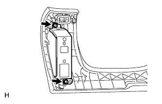
Install the bracket to the No. 1 instrument panel safety pad with the 2 screws.
-
Install the switch to the No. 1 instrument panel safety pad.
-
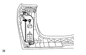
Install the screw.
-
Connect the connector.
-
-
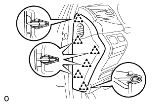
INSTALL NO. 1 INSTRUMENT PANEL SAFETY PAD SUB-ASSEMBLY
-
Connect each connector.
-
Attach the 5 clips and claw to install the No. 1 instrument panel safety pad sub-assembly.
-
Install the screw <C> and bolt.
-
Attach the claw to install the switch base hole cover to the No. 1 instrument panel safety pad sub-assembly.
-
-
INSTALL SWITCH BASE HOLE COVER
-
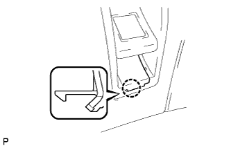
Attach the claw and install the cover to the instrument panel safety pad.
-
-
INSTALL INSTRUMENT PANEL ORNAMENT
-
Connect the connector.
-
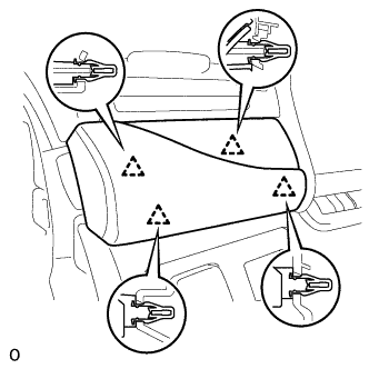
Attach the 4 clips to install the instrument panel ornament.
-
-
INSTALL INSTRUMENT SIDE PANEL LH (for LHD)
-
Attach the 6 clips to install the instrument side panel LH.
-
-
INSTALL INSTRUMENT SIDE PANEL RH (for RHD)
-
CONNECT CABLE TO NEGATIVE BATTERY TERMINAL
-
INSTALL COWL TOP VENTILATOR LOUVER
-

for LHD:
Install the 6 clips and cowl top ventilator louver RH.
Note
If the cowl top ventilator louver RH is not properly installed, water may leak into the engine room and cause malfunctions. Therefore, make sure the cowl top ventilator louver RH is installed properly.
-

for RHD:
Install the 6 clips and cowl top ventilator louver LH.
Note
If the cowl top ventilator louver LH is not properly installed, water may leak into the engine room and cause malfunctions. Therefore, make sure the cowl top ventilator louver LH is installed properly.
-
-
INSPECT SRS WARNING LIGHT
-
PERFORM INITIALIZATION
Note
Certain systems need to be initialized after disconnecting and reconnecting the cable from the negative (-) battery terminal.