ELECTRIC PARKING BRAKE SYSTEM Electric Parking Brake AUTO Switch Light Circuit
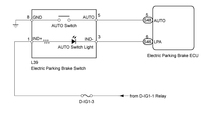
WIRING DIAGRAM
INSPECTION PROCEDURE
Note
-
If the electric parking brake ECU or parking brake with bracket actuator assembly is replaced, perform the "Reset Memory" and "ACQUIRE TENSION SENSOR ZERO POINT" procedures Click here.
-
Before disconnecting connectors or fuses, turn the engine switch off and wait 20 seconds or more.
Tech Tips
This flowchart is the inspection method for when the AUTO switch light of the electric parking brake continuously illuminates.
PROCEDURE
-
CHECK AUTO SWITCH (DATA LIST)
-
Turn the engine switch off.
-
Connect the intelligent tester to the DLC3.
-
Turn the engine switch on (IG) and the tester ON.
-
Enter the following menus:
Select: Chassis / Electric Parking Brake / Data List /
-
Check the values by referring to the table below.
Electric Parking Brake Tester Display Measurement Item/ Range Switch Condition Normal Condition AUTO Switch AUTO switch input information display/
ON or OFF
Engine switch on (IG)
AUTO switch is pressed and held
ON: AUTO switch is pressed and held
OFF: AUTO switch OFF (released)
OK On tester screen, item changes between ON and OFF according to switch operation. Result Result Proceed to NG A OK B
B 
CHECK HARNESS AND CONNECTOR (ECU - SWITCH) Click here
A 
-
-
INSPECT ELECTRIC PARKING BRAKE SWITCH (AUTO SWITCH)
-
Remove the electric parking brake switch Click here.
-
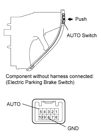
Measure the resistance according to the value(s) in the table below.
Standard resistance Tester Connection Switch Condition Specified Condition 5 (AUTO) - 8 (GND) AUTO switch is pressed and held Below 1 Ω AUTO switch OFF (released) 1 MΩ or higher
NG 
REPLACE ELECTRIC PARKING BRAKE SWITCH Click here
OK
-
-
CHECK HARNESS AND CONNECTOR (ECU - SWITCH)
-
Disconnect the S48 ECU connector.
-
Disconnect the L39 switch connector.
-
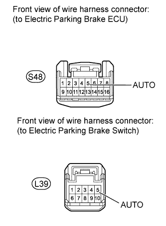
Measure the resistance according to the value(s) in the table below.
Standard resistance Tester Connection Condition Specified Condition S48-5 (AUTO) - L39-5 (AUTO) Always Below 5 Ω S48-5 (AUTO) - Body ground Always 100 kΩ or higher
NG
REPAIR OR REPLACE HARNESS OR CONNECTOR
OK
-
-
CHECK HARNESS AND CONNECTOR (ECU - SWITCH)
-
Disconnect the S46 ECU connector.
-
Disconnect the L39 switch connector.
-
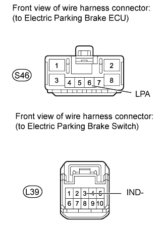
Measure the resistance according to the value(s) in the table below.
Standard resistance Tester Connection Condition Specified Condition S46-6 (LPA) - L39-3 (IND-) Always Below 5 Ω S46-6 (LPA) - Body ground Always 100 kΩ or higher
NG
REPAIR OR REPLACE HARNESS OR CONNECTOR
OK 
REPLACE ELECTRIC PARKING BRAKE ECU Click here
-