ELECTRIC PARKING BRAKE SYSTEM, Diagnostic DTC:C13A2/22

| DTC Code | DTC Name |
|---|---|
| C13A2/22 | Engine / Power Switch Malfunction |
DESCRIPTION
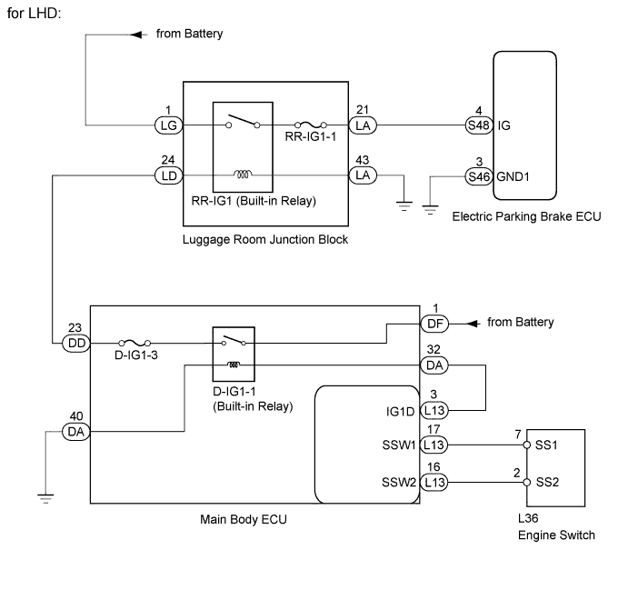
for LHD:
When the engine switch is turned on (IG), the IG operation power supply is output from the main body ECU. Power is then supplied from the luggage room junction block's RR-IG1 relay, which turns the RR-IG1 relay ON. Power is then supplied to the electric parking brake ECU.
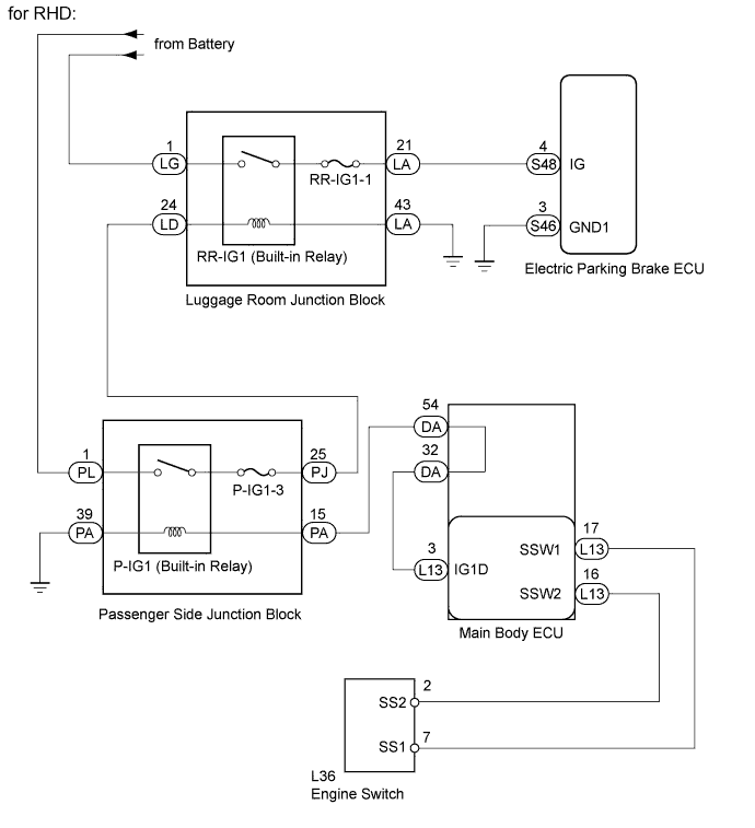
for RHD:
When the engine switch is turned on (IG), the IG operation power supply is output from the main body ECU and the passenger side junction block's P-IG1 relay turns ON. Power is then supplied from the P-IG1 relay to the luggage room junction block's RR-IG1 relay, which turns the RR-IG1 relay ON. Power is then supplied to the electric parking brake ECU.
| DTC Code | Detection Condition | Trouble Area |
|---|---|---|
| C13A2/22 | Both of following conditions are met:
|
|
WIRING DIAGRAM
INSPECTION PROCEDURE
Note
-
If the electric parking brake ECU or parking brake with bracket actuator assembly is replaced, perform the "Reset Memory" and "ACQUIRE TENSION SENSOR ZERO POINT" procedures Click here.
-
Before disconnecting connectors or fuses, turn the engine switch off and wait 20 seconds or more.
PROCEDURE
-
CHECK IG VOLTAGE (DATA LIST)
-
Turn the engine switch off.
-
Connect the intelligent tester to the DLC3.
-
Turn the engine switch on (IG) and the tester ON.
-
Enter the following menus:
Select: Chassis / Electric Parking Brake / Data List /
-
Check the values by referring to the table below.
Electric Parking Brake Tester Display Measurement Item/Range Switch Condition Normal Condition IG Status Engine switch information display/
ON or OFF
Engine switch on (IG) ON IG Switch IG power source information display/
ON or OFF
Engine switch on (IG) ON OK On tester screen, item changes between ON and OFF according to switch operation.
NG 
INSPECT FUSE Click here
OK 
-
-
CHECK DTC
-
Check for DTC Click here.
Result Result Proceed to C13A2/22 is output A DTC is not output B
B 
USE SIMULATION METHOD TO CHECK Click here
A 
REPLACE ELECTRIC PARKING BRAKE ECU Click here
-
-
INSPECT FUSE
-
Remove the RR-IG1-1fuse from the luggage room junction block.
-
for LHD:
-
Remove the D-IG1-3 fuse from the main body ECU.
-
-
for RHD:
-
Remove the P-IG1-3 fuse from the passenger side junction block.
-
-
Measure the resistance according to the value(s) in the table below.
Standard resistance Tester Connection Condition Specified Condition RR-IG1-1 fuse Always Below 1 Ω for LHD Tester Connection Condition Specified Condition D-IG1-3 fuse Always Below 1 Ω for RHD Tester Connection Condition Specified Condition P-IG1-3 fuse Always Below 1 Ω
NG
CHECK FOR SHORT IN ALL HARNESSES AND CONNECTORS CONNECTED TO FUSE AND REPLACE FUSE
OK
-
-
CHECK HARNESS AND CONNECTOR (ECU - LUGGAGE ROOM JUNCTION BLOCK AND BODY GROUND)
-
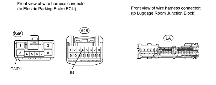
Disconnect the S46 and S48 ECU connector.
-
Disconnect the LA luggage room junction block connector.
-
Measure the resistance according to the value(s) in the table below.
Standard resistance Tester Connection Condition Specified Condition S48-4 (IG) - LA-21 Always Below 1 Ω S48-4 (IG) - Body ground Always 10 kΩ or higher S46-3 (GND1) - Body ground Always Below 1 Ω LA-43 - Body ground Always Below 1 Ω
NG
REPAIR OR REPLACE HARNESS OR CONNECTOR
OK
-
-
CHECK LUGGAGE ROOM JUNCTION BLOCK (RR-IG1 RELAY)
-
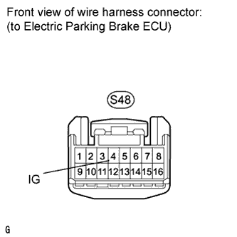
Disconnect the S48 ECU connector.
-
Measure the voltage according to the value(s) in the table below.
Standard voltage Tester Connection Switch Condition Specified Condition S48-4 (IG) - Body ground Engine switch on (IG) 11 to 14 V Result Result Proceed to NG A OK B
B
REPLACE ELECTRIC PARKING BRAKE ECU Click here
A
-
-
CHECK HARNESS AND CONNECTOR (LUGGAGE ROOM JUNCTION BLOCK - BATTERY)
-
Disconnect the LG luggage room junction block connector.
-
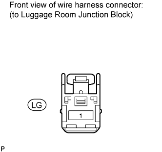
Measure the voltage according to the value(s) in the table below.
Standard voltage Tester Connection Condition Specified Condition LG-1 - Body ground Always 11 to 14 V
NG
REPAIR OR REPLACE HARNESS OR CONNECTOR
OK
-
-
CHECK HARNESS AND CONNECTOR (LUGGAGE ROOM JUNCTION BLOCK - BATTERY)
-
Disconnect the LD luggage room junction block connector.
-
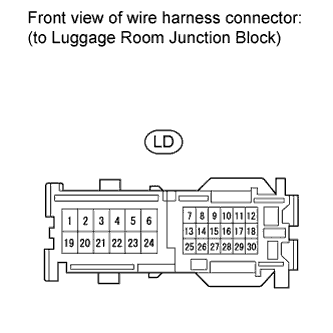
Measure the voltage according to the value(s) in the table below.
Standard voltage Tester Connection Switch Condition Specified Condition LD-24 - Body ground Engine switch on (IG) 11 to 14 V Result Result Proceed to NG (for LHD) A NG (for RHD) B OK C
B
CHECK HARNESS AND CONNECTOR (LUGGAGE ROOM JUNCTION BLOCK - PASSENGER SIDE JUNCTION BLOCK) Click here
C
REPLACE LUGGAGE ROOM JUNCTION BLOCK
A
-
-
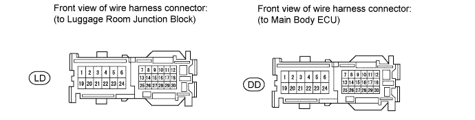
CHECK HARNESS AND CONNECTOR (LUGGAGE ROOM JUNCTION BLOCK - MAIN BODY ECU)
-
Disconnect the LD luggage room junction block connector.
-
Disconnect the DD main body ECU connector.
-
Measure the resistance according to the value(s) in the table below.
Standard resistance Tester Connection Condition Specified Condition LD-24 - DD-23 Always Below 1 Ω LD-24 - Body ground Always 10 kΩ or higher Result Result Proceed to NG A OK (1UR-FSE) B OK (1UR-FE) C
B
GO TO ENTRY AND START SYSTEM (Power Source Mode does not Change) Click here
C
GO TO ENTRY AND START SYSTEM (Power Source Mode does not Change) Click here
A
REPAIR OR REPLACE HARNESS OR CONNECTOR
-
-
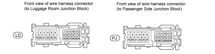
CHECK HARNESS AND CONNECTOR (LUGGAGE ROOM JUNCTION BLOCK - PASSENGER SIDE JUNCTION BLOCK)
-
Disconnect the LD luggage room junction block connector.
-
Disconnect the PJ passenger side junction block connector.
-
Measure the resistance according to the value(s) in the table below.
Standard resistance Tester Connection Condition Specified Condition LD-24 - PJ-25 Always Below 1 Ω LD-24 - Body ground Always 10 kΩ or higher
NG
REPAIR OR REPLACE HARNESS OR CONNECTOR
OK
-
-
CHECK HARNESS AND CONNECTOR (PASSENGER SIDE JUNCTION BLOCK - BATTERY)
-
Disconnect the PL passenger side junction block connector.
-
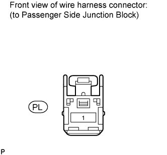
Measure the voltage according to the value(s) in the table below.
Standard voltage Tester Connection Condition Specified Condition PL-1 - Body ground Always 11 to 14 V
NG
REPAIR OR REPLACE HARNESS OR CONNECTOR
OK
-
-
CHECK HARNESS AND CONNECTOR (PASSENGER SIDE JUNCTION BLOCK - BODY GROUND)
-
Disconnect the PA passenger side junction block connector.
-
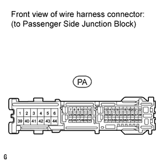
Measure the resistance according to the value(s) in the table below.
Standard resistance Tester Connection Condition Specified Condition PA-39 - Body ground Always Below 1 Ω
NG
REPAIR OR REPLACE HARNESS OR CONNECTOR
OK
-
-
CHECK HARNESS AND CONNECTOR (PASSENGER SIDE JUNCTION BLOCK - MAIN BODY ECU)
-
Disconnect the PA passenger side junction block connector.
-
Measure the voltage according to the value(s) in the table below.
Standard voltage Tester Connection Switch Condition Specified Condition PA-15 - Body ground Engine switch on (IG) 11 to 14 V Result Result Proceed to NG A OK B
B
REPLACE PASSENGER SIDE JUNCTION BLOCK
A
-
-
CHECK HARNESS AND CONNECTOR (PASSENGER SIDE JUNCTION BLOCK - MAIN BODY ECU)
-
Disconnect the PA passenger side junction block connector.
-
Disconnect the DA main body ECU connector.
-
Measure the resistance according to the value(s) in the table below.
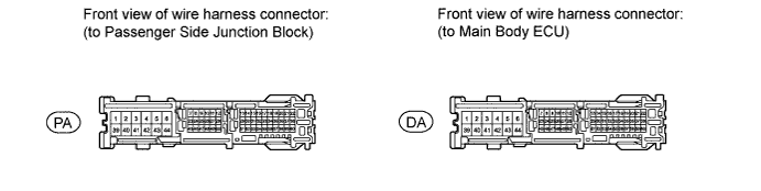
Standard resistance Tester Connection Condition Specified Condition PA-15 - DA-54 Always Below 1 Ω PA-15 - Body ground Always 10 kΩ or higher Result Result Proceed to NG A OK (1UR-FSE) B OK (1UR-FE) C
B
GO TO ENTRY AND START SYSTEM (Power Source Mode does not Change) Click here
C
GO TO ENTRY AND START SYSTEM (Power Source Mode does not Change) Click here
A
REPAIR OR REPLACE HARNESS OR CONNECTOR
-