BRAKE MASTER CYLINDER (for RHD) ON-VEHICLE INSPECTION

Note
A DTC may be stored during the inspection procedure. Be sure to clear the DTC and check that a normal system code is output after the inspection is finished.
-
CHECK BRAKE MASTER CYLINDER
-
Check battery voltage.
Standard voltage 11 to 14 V (while the engine switch is off) -
Connect intelligent tester and pedal effort gauge.
-
Connect the pedal effort gauge.
-
Move the shift lever to the P position. Apply the parking brake and connect the intelligent tester to the DLC3.
-
Turn the engine switch on (IG).
-
Clear the DTCs Click here.
-
-
Check operation without brake booster.
-
Check and adjust the brake pedal height Click here.
-
Check and adjust the brake pedal stroke sensor Click here.
-
Check the brake pedal free play Click here.
-
Check the brake pedal reserve distance Click here.
-
Turn the intelligent tester on and select: Electronically Controlled Brake system Invalid to prohibit the brake control.
-
Monitor "Voltage of Master Cylinder Sensor", "Voltage of Master Cylinder Sensor 2", "Stroke Sensor" and "Stroke Sensor 2" using the intelligent tester.
-
Check the value output from "Voltage of Master Cylinder Sensor", "Voltage of Master Cylinder Sensor 2", "Stroke Sensor" and "Stroke Sensor 2" by depressing the brake pedal.
Standard voltage Pedal Effort
N (kgf, lbf)
Voltage of Master Cylinder Sensor
(V)
Voltage of Master Cylinder Sensor 2
(V)
Stroke Sensor
(V)
Stroke Sensor 2
(V)
200 (20.4, 45) 0.87 to 1.27 0.92 to 1.32 1.19 to 1.59 3.37 to 3.77 500 (51,112) 1.91 to 2.31 1.95 to 2.35 1.54 to 1.94 3.02 to 3.42 -
Finish the brake control prohibition on the intelligent tester.
-
-
-
CHECK STROKE SIMULATOR
-
Check battery voltage.
Standard voltage 11 to 14 V (while the engine switch is off) -
Connect intelligent tester and pedal effort gauge.
-
Connect the pedal effort gauge.
-
Move the shift lever to the P position. Apply the parking brake and connect the intelligent tester to the DLC3.
-
Turn the engine switch on (IG).
-
Clear the DTCs Click here.
-
-
Check operation without brake booster.
-
Check and adjust the brake pedal height Click here.
-
Check and adjust the brake pedal stroke sensor Click here.
-
Check the brake pedal free play Click here.
-
Check the brake pedal reserve distance Click here.
-
Turn the intelligent tester on and select: Electronically Controlled Brake system Invalid to prohibit the brake control.
-
Monitor "Voltage of Master Cylinder Sensor", "Voltage of Master Cylinder Sensor 2", "Stroke Sensor" and "Stroke Sensor 2" using the intelligent tester.
-
Check the value output from "Voltage of Master Cylinder Sensor", "Voltage of Master Cylinder Sensor 2", "Stroke Sensor" and "Stroke Sensor 2" by depressing the brake pedal.
Standard voltage Pedal Effort
N (kgf, lbf)
Voltage of Master Cylinder Sensor
(V)
Voltage of Master Cylinder Sensor 2
(V)
Stroke Sensor
(V)
Stroke Sensor 2
(V)
200 (20.4, 45) 0.87 to 1.27 0.92 to 1.32 1.19 to 1.59 3.37 to 3.77 500 (51,112) 1.91 to 2.31 1.95 to 2.35 1.54 to 1.94 3.02 to 3.42 -
Finish the brake control prohibition on the intelligent tester.
-
-
Check operation with brake booster
-
Turn the engine switch on (IG).
-
Turn on the intelligent tester and monitor the value of "Stroke Sensor" and "Stroke Sensor 2".
-
Depress the brake pedal 4 or 5 times.
-
Check the value output from "Stroke Sensor" and "Stroke Sensor 2" by depressing the brake pedal.
Standard voltage Pedal Effort
N (kgf, lbf)
Stroke Sensor
(V)
Stroke Sensor 2
(V)
50 (5.1 11) 1.04 to 1.44 3.52 to 3.92 100 (10.2, 22) 1.13 to 1.53 3.38 to 3.78 150 (15.3, 34) 1.27 to 1.67 3.29 to 3.69 200 (20.4, 45) 1.34 to 1.74 3.22 to 3.62
-
-
-
CHECK BRAKE FLUID LEVEL WARNING SWITCH
-
Remove the reservoir filler cap and strainer.
-
Disconnect the brake fluid level warning switch connector.
-
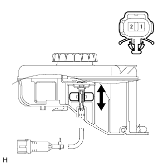
Measure the resistance of the switch.
Tech Tips
There is a float inside the reservoir. Its position can be changed by increasing or decreasing the brake fluid level.
Standard resistance Tester Connection Condition Specified Condition 1 - 2 Float up (Switch OFF) 1.84 to 2.16 kΩ 1 - 2 Float down (Switch ON) Below 1 Ω If the value is not as specified, replace the brake fluid reservoir.
-
Add brake fluid to the MAX level.
-