BRAKE PEDAL SUPPORT (for RHD) INSTALLATION

Tech Tips
-
The following procedures are for RHD vehicles.
-
For LHD vehicles, refer to the procedures for LHD vehicles Click here.
Note
While the battery is connected, even if the engine switch is off, the brake control system activates when the brake pedal is depressed or the door courtesy switch turns on. Therefore during servicing of the brake system components, do not operate the brake pedal and open/close the doors while the battery is connected.
-
INSTALL BRAKE PEDAL SUPPORT ASSEMBLY
-
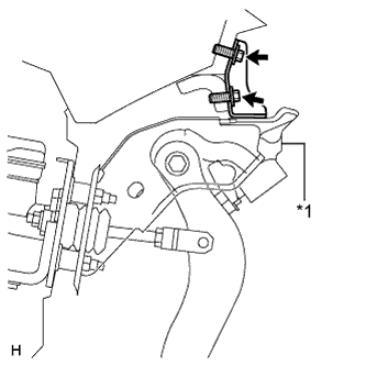
Text in Illustration *1 Brake Pedal Support Install the brake pedal support with the 2 bolts.
- Torque:
- 19 N*m { 195 kgf*cm, 14 ft.*lbf }
-
Install the 4 nuts.
- Torque:
- 13 N*m { 130 kgf*cm, 9 ft.*lbf }
-
-
INSTALL PUSH ROD PIN
-
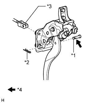
Text in Illustration *1 Push Rod Pin *2 Clip *3 Push Rod Clevis *4 Lithium soap base glycol grease Apply a light coat of lithium soap base glycol grease to the push rod pin.
-
Set the master cylinder push rod clevis in place, insert the push rod pin from outside of the vehicle and then install a new clip.
-
-
INSTALL BRAKE PEDAL RETURN SPRING
-
Install the spring between the pedal and steering column.
-
-
CONNECT CONNECTORS
-
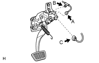
Connect the stop light switch connector (labeled A) and then attach the wire harness clamp (labeled B).
-
Connect the brake pedal stroke sensor connector (labeled C).
-
-
CHECK BRAKE DRAG
-
CHECK AND ADJUST BRAKE PEDAL
-
INSTALL INSTRUMENT PANEL SAFETY PAD SUB-ASSEMBLY
-
CONNECT CABLE TO NEGATIVE BATTERY TERMINAL
Note
When disconnecting the cable, some systems need to be initialized after the cable is reconnected Click here.
-
INSTALL COWL TOP VENTILATOR LOUVER
-

for LHD:
Install the 6 clips and cowl top ventilator louver RH.
Note
If the cowl top ventilator louver RH is not properly installed, water may leak into the engine room and cause malfunctions. Therefore, make sure the cowl top ventilator louver RH is installed properly.
-

for RHD:
Install the 6 clips and cowl top ventilator louver LH.
Note
If the cowl top ventilator louver LH is not properly installed, water may leak into the engine room and cause malfunctions. Therefore, make sure the cowl top ventilator louver LH is installed properly.
-
-
CHECK SRS WARNING LIGHT