BRAKE PEDAL SUPPORT (for RHD) ADJUSTMENT

Tech Tips
-
The following procedures are for RHD vehicles.
-
For LHD vehicles, refer to the procedures for LHD vehicles Click here.
-
CHECK AND ADJUST BRAKE PEDAL HEIGHT
Note
Fold back the carpet below the brake pedal for this inspection adjustment.
-
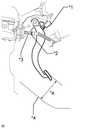
Text in Illustration *1 Stop Light Switch *2 Push Rod Clevis Lock Nut *3 Push Rod *4 Asphalt Sheet *a Pedal Height Check the brake pedal height.
Standard pedal height from asphalt sheet 196.2 to 206.2 mm (7.72 to 8.11 in.) -
Adjust the pedal height.
-
Disconnect the connector from the stop light switch.
-
Loosen the stop light switch lock nut and turn the switch so that the pedal has free play.
-
Loosen the push rod clevis lock nut.
-
Adjust the pedal height by turning the push rod.
Standard pedal height from asphalt sheet 196.2 to 206.2 mm (7.72 to 8.11 in.) -
Tighten the push rod clevis lock nut.
- Torque:
- 26 N*m { 265 kgf*cm, 19 ft.*lbf }
-
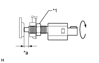
Text in Illustration *1 Stop Light Switch Lock Nut *a 1.5 to 2.6 mm (0.0591 to 0.102 in.) Turn the stop light switch so that its protrusion is between 1.5 and 2.6 mm (0.0591 and 0.102 in.). Then tighten the lock nut.
- Torque:
- 17 N*m { 170 kgf*cm, 12 ft.*lbf }
-
Connect the stop light switch connector.
-
Without depressing the brake pedal, check that the stop light does not illuminate. If it illuminates, adjust the brake pedal height again.
-
Push the brake pedal in 5 to 10 mm (0.197 to 0.394 in.), and check that the stop light comes on.
If the stop light does not turn on, adjust the brake pedal height again.
-
-
-
ADJUST BRAKE PEDAL STROKE SENSOR
-
Connect the intelligent tester to the DLC3 with the engine switch off.
-
Loosen the 2 bolts.
-
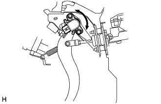
Turn the engine switch on (IG). While reading the stroke sensor 1 value shown on the intelligent tester, turn the stroke sensor slowly to the right and left to adjust it to the standard voltage.
Standard voltage 0.8 to 1.2 V -
Tighten the 2 bolts.
- Torque:
- 8.5 N*m { 87 kgf*cm, 75 in.*lbf }
Note
Do not depress the brake pedal while performing the linear valve offset learning, as this may cause a DTC to be stored.
-
Perform the linear valve offset learning Click here.
-
-
CHECK BRAKE PEDAL FREE PLAY
-
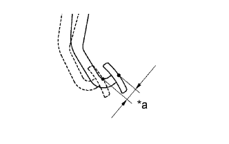
Text in Illustration *a Pedal Free Play Press the pedal until a slight resistance is felt.
Measure the distance as shown in the illustration.
Standard pedal free play 1.0 to 2.0 mm (0.0394 to 0.0787 in.) If the pedal free play is 1.0 mm (0.0394 in) or less, check the protrusion of the stop light switch shaft.
Protrusion of the stop light switch shaft 1.5 to 2.6 mm (0.0591 to 0.102 in.) If the protrusion is not within the specified value range, adjust it.
If the protrusion is within the specified value range, troubleshoot the brake system and proceed to the Check Brake Pedal Reserve Distance procedure.
-
-
CHECK BRAKE PEDAL RESERVE DISTANCE
-
Release the parking brake. Start the engine.
-
Depress the brake pedal and check the pedal reserve distance as follows.
Pedal reserve distance from asphalt sheet at 500 N (51 kgf, 112.0 lbf) More than 147 mm (5.79 in.) If the distance is not as specified, troubleshoot the brake system.
Tech Tips
Check the brake pedal reserve distance at the same location as that used when checking the brake pedal height.
-