FRONT BRAKE FLEXIBLE HOSE INSTALLATION

Tech Tips
-
Use the same procedures for the LH side and RH side.
-
The procedures listed below are for the LH side.
Note
While the battery is connected, even if the engine switch is off, the brake control system activates when the brake pedal is depressed or the door courtesy switch turns on. Therefore during servicing of the brake system components, do not operate the brake pedal and open/close the doors while the battery is connected.
-
INSTALL FRONT BRAKE FLEXIBLE HOSE
-
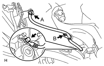
Connect the flexible hose with a new union bolt (labeled C) and a new gasket.
Tech Tips
This illustration shows vehicles that are not equipped with a 6-pot caliper. For vehicles equipped with a 6-pot caliper, the shape of the parts differs slightly.
- Torque:
- 39 N*m { 400 kgf*cm, 29 ft.*lbf }
Note
Install the flexible hose lock securely in the lock hole in the disc brake caliper.
-
Install the clamp bolt (labeled B).
- Torque:
- 20 N*m { 204 kgf*cm, 15 ft.*lbf }
-
Connect the brake tube to the flexible hose with union nut wrench while holding the flexible hose with a wrench.
- Torque:
- 15 N*m { 155 kgf*cm, 11 ft.*lbf }
Note
-
Do not bend or damage the brake tube.
-
Do not allow any foreign matter such as dirt and dust to enter the brake tube from the connecting points.
-
Use the formula to calculate special torque values for situations where a union nut wrench is combined with a torque wrench Click here.
-
Install the flexible hose with a new clip (labeled A).
Note
Securely install the clip.
-
-
CONNECT CABLE TO NEGATIVE BATTERY TERMINAL
Note
When disconnecting the cable, some systems need to be initialized after the cable is reconnected Click here.
-
INSTALL COWL TOP VENTILATOR LOUVER
-

for LHD:
Install the 6 clips and cowl top ventilator louver RH.
Note
If the cowl top ventilator louver RH is not properly installed, water may leak into the engine room and cause malfunctions. Therefore, make sure the cowl top ventilator louver RH is installed properly.
-

for RHD:
Install the 6 clips and cowl top ventilator louver LH.
Note
If the cowl top ventilator louver LH is not properly installed, water may leak into the engine room and cause malfunctions. Therefore, make sure the cowl top ventilator louver LH is installed properly.
-
-
BLEED BRAKE LINE
-
Bleed brake line.
-
Remove the brake master cylinder reservoir filler cap assembly.
-
Add brake fluid into the reservoir between MAX and MIN level on the brake fluid reservoir.
Brake fluid SAE J1703 or FMVSS No. 116 DOT3 -
Connect the intelligent tester to the DLC3 and turn the power switch on (IG).
-
Turn the intelligent tester on and enter the following menus: Chassis / ABS/VSC/TRC / Utility / Air Bleeding.
-
Select the "Usual air bleeding / All Line" and bleed brake line according to the intelligent tester display.
-
After air bleeding, tighten each bleeder plug.
- Torque:
- for Front Brake (except 6-pot caliper)
- 11 N*m { 110 kgf*cm, 8 ft.*lbf }
- for Front Brake (6-pot caliper)
- 19 N*m { 194 kgf*cm, 14 ft.*lbf }
- for Rear Brake
- 11 N*m { 110 kgf*cm, 8 ft.*lbf }
-
-
Clear the DTCs Click here.
-
Turn the intelligent tester off and turn the power switch off.
-
Inspect for brake fluid leaks.
-
Adjust the brake fluid level in the reservoir Click here.
-
-
INSTALL FRONT WHEEL
- Torque:
- 140 N*m { 1428 kgf*cm, 103 ft.*lbf }
-
CLEAR DTC
-
CHECK FOR DTC
-
If any DTC is set, perform the troubleshooting for that DTC Click here.
-