SKID CONTROL ECU (for RHD) INSTALLATION

Tech Tips
-
The following procedures are for RHD vehicles.
-
For LHD vehicles, refer to the procedures for LHD vehicles Click here.
Note
While the battery is connected, even if the engine switch is off, the brake control system activates when the brake pedal is depressed or the door courtesy switch turns on. Therefore during servicing of the brake system components, do not operate the brake pedal and open/close the doors while the battery is connected.
-
INSTALL SKID CONTROL ECU BRACKET
-
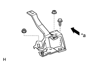
Text in Illustration *a Front Install the bracket with the bolt and 2 nuts.
- Torque:
- 8.5 N*m { 87 kgf*cm, 75 in.*lbf }
-
-
INSTALL SKID CONTROL ECU
-
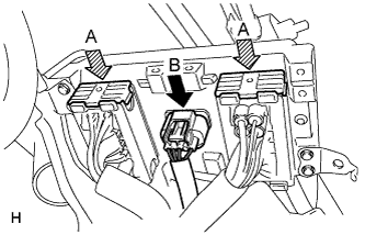
Connect the 2 connectors (labeled A) and press the lock levers down to lock the connectors.
Note
Make sure that the lock levers securely lock the connectors.
-
Connect the connector (labeled B).
-
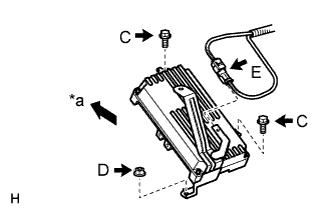
Text in Illustration *a Front Install the ECU with the 2 bolts (labeled C) and nut (labeled D).
- Torque:
- 8.5 N*m { 87 kgf*cm, 75 in.*lbf }
-
Connect the short connector for the brake stroke simulator (labeled E) to the bracket of the skid control ECU.
-
-
CONNECT CABLE TO NEGATIVE BATTERY TERMINAL
Note
When disconnecting the cable, some systems need to be initialized after cable is reconnected Click here.
-
INSTALL COWL TOP VENTILATOR LOUVER
-

for LHD:
Install the 6 clips and cowl top ventilator louver RH.
Note
If the cowl top ventilator louver RH is not properly installed, water may leak into the engine room and cause malfunctions. Therefore, make sure the cowl top ventilator louver RH is installed properly.
-

for RHD:
Install the 6 clips and cowl top ventilator louver LH.
Note
If the cowl top ventilator louver LH is not properly installed, water may leak into the engine room and cause malfunctions. Therefore, make sure the cowl top ventilator louver LH is installed properly.
-
-
CHECK AND CLEAR DTC
-
PERFORM LINEAR VALVE OFFSET LEARNING
-
PERFORM YAW RATE SENSOR ZERO POINT CALIBRATION
-
PERFORM TEST MODE INSPECTION
-
INSTALL ENGINE ROOM SIDE COVER RH
-
Install the engine room side cover RH with the 5 clips.
-
-
INSTALL V-BANK COVER SUB-ASSEMBLY
-
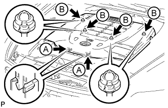
Slide the cover from the vehicle front toward the rear of the vehicle to attach the 2 clips labeled A, and then attach the 4 clips labeled B to install the V bank cover sub-assembly.
Note
-
Make sure the clips are attached securely.
-
Attaching the clips forcefully or hitting the top of the clips may damage them.
-
When attaching the clips labeled A, be sure to slide the cover from the front of the vehicle toward the rear of the vehicle.
-
-