FRONT SPEED SENSOR (for 2WD) INSTALLATION

Tech Tips
-
The front speed sensor is a component of the front axle hub sub-assembly. If the sensor malfunctions, replace the front axle hub sub-assembly.
-
The procedures listed below are for the RH side.
-
Use the same procedures for the LH side and RH side.
Note
While the battery is connected, even if the engine switch is off, the brake control system activates when the brake pedal is depressed or the door courtesy switch turns on. Therefore during servicing of the brake system components, do not operate the brake pedal and open/close the doors while the battery is connected.
-
INSTALL FRONT AXLE HUB SUB-ASSEMBLY
Tech Tips
The front speed sensor is a component of the front axle hub sub-assembly. If the sensor malfunctions, replace the front axle hub sub-assembly.
-
Install the front axle hub Click here.
-
-
CHECK FRONT AXLE HUB BEARING LOOSENESS
-
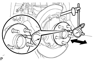
Using a dial indicator, measure the looseness near the center of the axle hub.
Maximum 0.05 mm (0.0020 in.) Note
Ensure that the dial indicator is set at a right angle to the measurement surface.
If the looseness exceeds the maximum, replace the axle hub.
-
-
CHECK FRONT AXLE HUB RUNOUT
-
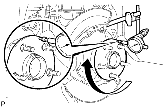
Using a dial indicator, measure the runout on the surface of the axle hub outside the hub bolt.
Maximum 0.05 mm (0.0020 in.) Note
Ensure that the dial indicator is set at a right angle to the measurement surface.
If the runout exceeds the maximum, replace the axle hub.
-
-
INSTALL FRONT DISC
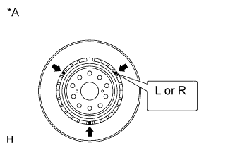
Text in Illustration *A for 18 inch Disc Note
The 18 inch disc has an identification mark. Make sure of the identification mark when installing the disc.
Item Identification mark 18 inch disc LH L 18 inch disc RH R Tech Tips
The 17 inch disc has no identification mark. The disc can be installed to the LH or RH side.
-
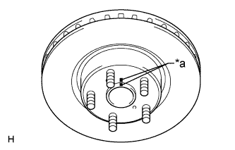
Text in Illustration *a Matchmark Align the matchmarks, and install the front disc.
Tech Tips
When replacing the front disc with a new one, select the installation position where the front disc has the minimum runout.
-
-
CONNECT FRONT DISC BRAKE CALIPER ASSEMBLY
-
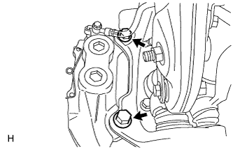
Install the disc brake caliper with 2 new bolts.
- Torque:
- 135 N*m { 1377 kgf*cm, 100 ft.*lbf }
-
-
INSTALL SKID CONTROL SENSOR WIRE
-
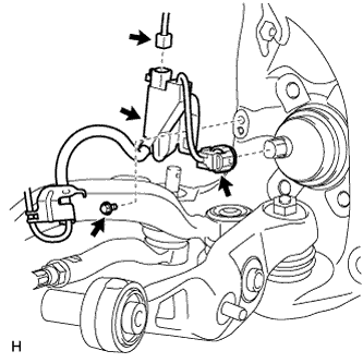
Connect the connector to the front speed sensor.
-
Install the sensor clamp with the bolt.
- Torque:
- 8.5 N*m { 87 kgf*cm, 75 in.*lbf }
-
Connect the pad wear indicator connector.
-
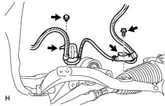
Install the 2 sensor clamps with the 2 bolts.
- Torque:
- 8.5 N*m { 87 kgf*cm, 75 in.*lbf }
Note
Do not twist the sensor wire when installing the clamps.
-
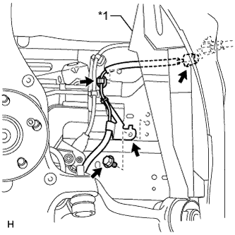
Text in Illustration *1 Front Fender Liner Install the sensor clamp with the bolt.
- Torque:
- 8.5 N*m { 87 kgf*cm, 75 in.*lbf }
Note
Do not twist the sensor wire when installing the clamp.
-
Attach the sensor clip.
-
Connect the sensor connector.
-
Connect the front fender liner.
-
-
INSTALL FRONT WHEEL
- Torque:
- 140 N*m { 1428 kgf*cm, 103 ft.*lbf }
-
CONNECT CABLE TO NEGATIVE BATTERY TERMINAL
Note
When disconnecting the cable, some systems need to be initialized after the cable is reconnected Click here.
-
INSTALL COWL TOP VENTILATOR LOUVER
-

for LHD:
Install the 6 clips and cowl top ventilator louver RH.
Note
If the cowl top ventilator louver RH is not properly installed, water may leak into the engine room and cause malfunctions. Therefore, make sure the cowl top ventilator louver RH is installed properly.
-

for RHD:
Install the 6 clips and cowl top ventilator louver LH.
Note
If the cowl top ventilator louver LH is not properly installed, water may leak into the engine room and cause malfunctions. Therefore, make sure the cowl top ventilator louver LH is installed properly.
-
-
CHECK SPEED SENSOR SIGNAL