BRAKE ACTUATOR (for RHD) INSPECTION

-
CHECK BRAKE ACTUATOR ASSEMBLY
-
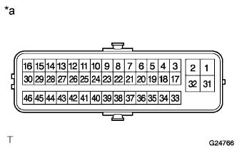
Text in Illustration *a Component without harness connected:
(Brake Actuator Assembly)
Measure the resistance according to the value(s) in the table below.
Tech Tips
Perform the check with the actuator at the lowest temperature possible.
Standard resistance Tester Connection Condition Specified Condition 37 (SMC1) - 36 (BS1) Always 15.3 to 25.0 Ω 19 (SMC2) - 20 (BS2) 44 (FRA+) - 43 (FRA-) 3.6 to 6.0 Ω 28 (FRR+) - 27 (FRR-) 35 (FLA+) - 38 (FLA-) 21 (FLR+) - 22 (FLR-) 39 (RRA+) - 40 (RRA-) 41 (RLA+) - 42 (RLA-) 23 (RRR+) - 24 (RRR-) 4.4 to 7.0 Ω 25 (RLR+) - 26 (RLR-) If the result is not as specified, replace the brake actuator.
-
-
CHECK BRAKE ACCUMULATOR PUMP
-
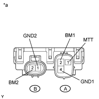
Text in Illustration *a Component without harness connected:
(Brake Accumulator Pump)
Measure the resistance according to the value(s) in the table below.
Standard resistance Tester Connection Condition Specified Condition A2 (BM1) - A4 (GND1) Always 10 Ω or less B2 (BM2) - A4 (GND1) A2 (BM1) - B2 (BM2) Below 1 Ω A4 (GND1) - B1 (GND2) A2 (BM1) - A1 (MTT) 950 to 1050 Ω B2 (BM2) - A1 (MTT) If the result is not as specified, replace the brake accumulator pump.
-