ELECTRONICALLY CONTROLLED BRAKE SYSTEM, Diagnostic DTC:C1377/43

| DTC Code | DTC Name |
|---|---|
| C1377/43 | Capacitor Malfunction |
DESCRIPTION
The brake control power supply (capacitor) is used as auxiliary power for brake control when battery voltage is low.
| DTC Code | Information Code | DTC Detection Condition | Trouble Area |
|---|---|---|---|
| C1377/43 | 101 | When both conditions below are met:
|
Brake control power supply |
| ↑ | 102 | When both conditions below are met:
|
↑ |
| ↑ | 103 | When both conditions below are met:
|
Positive battery circuit (Apply high voltage) |
| ↑ | 105 | When both conditions below are met:
|
Brake control power supply |
| ↑ | 106 | When both conditions below are met:
|
↑ |
| ↑ | 108 | When both conditions below are met:
|
↑ |
| ↑ | 109 | When both conditions below are met:
|
|
| ↑ | 110 | When both conditions below are met:
|
|
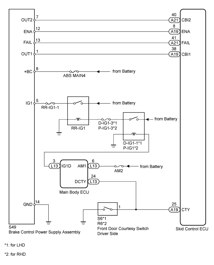
WIRING DIAGRAM
INSPECTION PROCEDURE
PROCEDURE
-
CHECK FREEZE FRAME DATA
-
Check the information code from the "FREEZE FRAME DATA" memorized when the DTC (C1377/43) is stored Click here.
Result Result Proceed to Information codes (109 and 110) are output A Information codes (101, 102, 105, 106 and 108) are output B Information code (103) is output C
B 
REPLACE BRAKE CONTROL POWER SUPPLY Click here
C 
INSPECT BATTERY Click here
A 
-
-
INSPECT FUSE (ABS MAIN4)
-
Remove the ABS MAIN4 fuse from the luggage room junction block.
-
Measure the resistance of the fuse.
Standard resistance Tester Connection Condition Specified Condition ABS MAIN4 fuse Always Below 1 Ω
NG
REPLACE FUSE
OK
-
-
INSPECT BRAKE CONTROL POWER SUPPLY (+BC AND GND TERMINAL)
-
Disconnect the S49 power supply connector.
-
Measure the voltage according to the value(s) in the table below.
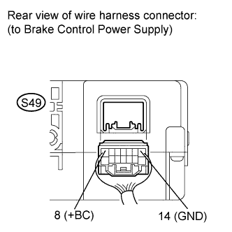
Standard voltage Tester Connection Condition Specified Condition S49-8 (+BC) - Body ground Always 11 to 14 V -
Measure the resistance according to the value(s) in the table below.
Standard resistance Tester Connection Condition Specified Condition S49-14 (GND) - Body ground Always Below 1 Ω
NG
REPAIR OR REPLACE HARNESS OR CONNECTOR (+BC OR GND CIRCUIT)
OK
-
-
INSPECT BRAKE CONTROL POWER SUPPLY (OUT1 AND OUT2 TERMINAL)
-
Measure the voltage according to the value(s) in the table below.
Tech Tips
Perform inspection while the brake is not operated.
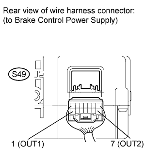
Standard voltage Tester Connection Condition Specified Condition S49-1 (OUT1) - Body ground While the brake is not operated 11 to 14 V S49-7 (OUT2) - Body ground While the brake is not operated 11 to 14 V
OK
RECONFIRM DTC Click here
NG
-
-
CHECK HARNESS AND CONNECTOR (SKID CONTROL ECU - BRAKE CONTROL POWER SUPPLY)
-
Disconnect the A19 and A21 ECU connectors.
-
Disconnect the S49 power supply connector.
-
Measure the resistance according to the value(s) in the table below.
Standard resistance Tester Connection Condition Specified Condition A19-38 (CBI1) - S49-1 (OUT1) Always Below 1 Ω A21-40 (CBI2) - S49-7 (OUT2) Always Below 1 Ω A19-38 (CBI1) - Body ground Always 10 kΩ or higher A21-40 (CBI2) - Body ground Always 10 kΩ or higher
OK
RECONFIRM DTC Click here
NG 
REPAIR OR REPLACE HARNESS OR CONNECTOR
-
-
INSPECT BATTERY
-
Check the battery voltage.
Result Result Proceed to OK
(Standard voltage: 11 to 14 V)
A for 1UR-FSE:
NG
B for 1UR-FE:
NG
C
B
INSPECT CHARGING SYSTEM (for 1UR-FSE) Click here
C
INSPECT CHARGING SYSTEM (for 1UR-FE) Click here
A
-
-
INSPECT BRAKE CONTROL POWER SUPPLY (+BC TERMINAL)
-
Disconnect the S49 power supply connector.
-
Measure the voltage according to the value(s) in the table below.
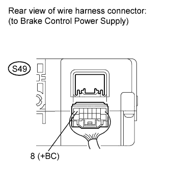
Standard voltage Tester Connection Condition Specified Condition S49-8 (+BC) - Body ground Always 11 to 14 V
NG
REPAIR OR REPLACE HARNESS OR CONNECTOR (+BC CIRCUIT)
OK
-
-
RECONFIRM DTC
-
Clear the DTC Click here.
-
Turn the engine switch on (IG).
-
Check if the same DTC is recorded Click here.
Tech Tips
Reinstall the sensors, connectors, etc. and restore the vehicle to its prior condition before rechecking for DTCs.
Result Result Proceed to DTC (C1377/43) is not output A DTC (C1377/43) is output B
B
REPLACE BRAKE CONTROL POWER SUPPLY Click here
A
END
-