ELECTRONICALLY CONTROLLED BRAKE SYSTEM, Diagnostic DTC:C1365/54

| DTC Code | DTC Name |
|---|---|
| C1365/54 | Accumulator Pressure Sensor Malfunction |
DESCRIPTION
The accumulator pressure sensor is built into the brake actuator.
The skid control ECU detects the accumulator pressure based on the data sent from the accumulator pressure sensor, and then runs and stops the pump motor by operating the motor relay.
| DTC Code | Information Code | DTC Detection Condition | Trouble Area |
|---|---|---|---|
| C1365/54 | 211 | Sensor power 1 (VCM1) voltage is 4.7 V or less or 5.3 V or more for at least 0.05 seconds. |
|
| ↑ | 212 | Accumulator pressure sensor output voltage is less than 0.25 or 4.53 V or more for at least 0.05 seconds. | ↑ |
| ↑ | 214 | While the motor is OFF, the total of the wheel cylinder pressure sensor values of all 4 wheels increases but the accumulator pressure changes little for 0.5 seconds or more. | ↑ |
| ↑ | 215 | The accumulator pressure sensor output voltage is stuck at 4.53 V or less. | ↑ |
WIRING DIAGRAM
Refer to DTCs C1246/46 and C1364/61 Click here.
INSPECTION PROCEDURE
Note
When replacing the skid control ECU or brake actuator, perform initialization of linear solenoid valve and calibration Click here.
PROCEDURE
-
CHECK HARNESS AND CONNECTOR (SKID CONTROL ECU - BRAKE ACTUATOR)
-
Disconnect the A19 ECU connector.
-
Disconnect the A27 actuator connector.
-
Measure the resistance according to the value(s) in the table below.
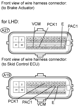
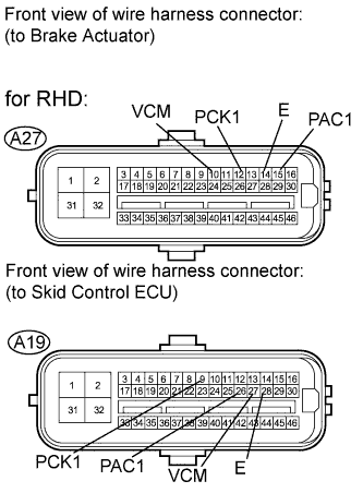
Standard resistance for LHD Tester Connection Condition Specified Condition A19-9 (PCK1) - A27-37 (PCK1) Always Below 1 Ω A19-26 (PAC1) - A27-46 (PAC1) Always Below 1 Ω A19-27 (VCM) - A27-35 (VCM) Always Below 1 Ω A19-28 (E) - A27-45 (E) Always Below 1 Ω for RHD Tester Connection Condition Specified Condition A19-9 (PCK1) - A27-12 (PCK1) Always Below 1 Ω A19-26 (PAC1) - A27-15 (PAC1) Always Below 1 Ω A19-27 (VCM) - A27-10 (VCM) Always Below 1 Ω A19-28 (E) - A27-14 (E) Always Below 1 Ω -
Measure the resistance according to the value(s) in the table below.
Standard resistance Tester Connection Condition Specified Condition A19-9 (PCK1) - Body ground Always 10 kΩ or higher A19-26 (PAC1) - Body ground Always 10 kΩ or higher A19-27 (VCM) - Body ground Always 10 kΩ or higher A19-28 (E) - Body ground Always 10 kΩ or higher
NG 
REPAIR OR REPLACE HARNESS OR CONNECTOR
OK 
-
-
RECONFIRM DTC
-
Clear the DTC Click here.
-
Turn the engine switch on (IG).
-
Check if the same DTC is recorded Click here.
Tech Tips
Reinstall the sensors, connectors, etc. and restore the vehicle to its prior condition before rechecking for DTCs.
Result Result Proceed to DTC (C1365/54) is output A DTC (C1365/54) is not output B
B
END
A
-
-
CHECK FREEZE FRAME DATA
-
Check the information code from the "FREEZE FRAME DATA" memorized when the DTC (C1365/54) is stored Click here.
Result Result Proceed to Sensor power supply voltage trouble code (211) is output A Sensor output value trouble codes (212, 214 and 215) are output B
B
REPLACE BRAKE ACTUATOR Click here
A 
REPLACE SKID CONTROL ECU Click here
-