ELECTRONICALLY CONTROLLED BRAKE SYSTEM Brake Hold Standby Indicator Light Circuit
DESCRIPTION
When the brake hold switch is turned ON while the engine switch is on (IG), if the brake hold operation is possible, the brake hold standby indicator light illuminates in green Click here.
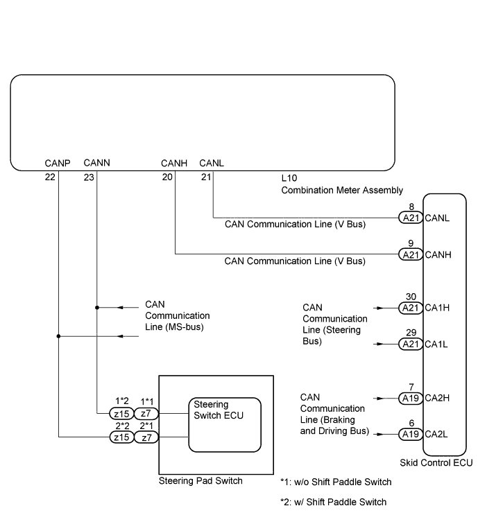
WIRING DIAGRAM
INSPECTION PROCEDURE
Note
When replacing the skid control ECU, perform initialization of linear solenoid valve and calibration Click here and Click here.
PROCEDURE
-
PRE-CHECK
-
If the brake hold standby indicator light does not illuminate even though the brake hold switch is pushed, check that the brake hold function operation conditions are met.
-
The driver's door is closed.
-
Driver's seat belt is fastened.
-
The engine hood is closed.
-
The trunk is closed.
-
The system is normal.
Tech Tips
If a malfunction occurs in one of the following systems, the brake hold operated indicator light will blink. If this occurs, perform troubleshooting on the malfunctioning system Click here.
-
Electronically Controlled Brake system
-
ABS system
-
VSC system
-
Electric parking brake system
-
SFI system
-
-
NEXT 
-
-
INSPECT CAN COMMUNICATION SYSTEM
-
for LHD:
Check if the CAN communication system DTC is output Click here.
for RHD:
Check if the CAN communication system DTC is output Click here.
Result Result Proceed to DTC is not output A DTC is output (for LHD) B DTC is output (for RHD) C
B 
GO TO CAN COMMUNICATION SYSTEM (for LHD) Click here
C
GO TO CAN COMMUNICATION SYSTEM (for RHD) Click here
A
-
-
PERFORM ACTIVE TEST USING INTELLIGENT TESTER (BRAKE HOLD STANDBY INDICATOR LIGHT)
-
Connect the intelligent tester to the DLC3.
-
Turn the engine switch on (IG).
-
Select the Active Test mode on the intelligent tester.
Meter ECU: Tester Display Test Part Control Range Diagnostic Note Indicat. Brake Hold Brake hold standby indicator light ON / OFF Observe combination meter -
Check that the brake hold standby indicator light turns on or off when using the intelligent tester.
OK The brake hold standby indicator light turns on or off in accordance with the intelligent tester. Tech Tips
If troubleshooting has been carried out according to the PROBLEM SYMPTOMS TABLE, refer back to the table and proceed to the next step before replacing the part Click here.
NG
GO TO METER / GAUGE SYSTEM Click here
OK
-
-
PERFORM ACTIVE TEST USING INTELLIGENT TESTER (BRAKE HOLD STANDBY INDICATOR LIGHT)
-
Connect the intelligent tester to the DLC3.
-
Turn the engine switch on (IG).
-
Select the Active Test mode on the intelligent tester.
Skid control ECU: Tester Display Test Part Control Range Diagnostic Note BH Standby Light Brake hold standby indicator light ON / OFF Observe combination meter -
Check that the brake hold standby indicator light turns on or off on the intelligent tester.
OK The brake hold standby indicator light turns on or off in accordance with the intelligent tester. Result Result Proceed to OK A NG (for LHD) B NG (for RHD) C
B
REPLACE SKID CONTROL ECU (for LHD) Click here
C
REPLACE SKID CONTROL ECU (for RHD) Click here
A
-
-
READ VALUE USING INTELLIGENT TESTER (STEERING PAD SWITCH)
-
Connect the intelligent tester to the DLC3.
-
Turn the engine switch on (IG).
-
Select the Data List mode on the intelligent tester.
Steering Pad Switch: Tester Display Measurement Item/
Range
Normal Condition Diagnostic Note Brake Hold Switch Brake hold switch / ON or OFF ON: Brake hold switch ON
OFF: Brake hold switch OFF
- -
Check that the brake hold switch turns on or off on the intelligent tester.
OK The brake hold switch is operated, and the display changes as shown above. Result Result Proceed to OK (for LHD) A OK (for RHD) B BG C
B
REPLACE SKID CONTROL ECU (for RHD) Click here
C
REPLACE STEERING PAD SWITCH
A 
REPLACE SKID CONTROL ECU (for LHD) Click here
-