ELECTRONICALLY CONTROLLED BRAKE SYSTEM, Diagnostic DTC:C1247/47, C1346/71, C1392/48

| DTC Code | DTC Name |
|---|---|
| C1247/47 | Stroke Sensor Malfunction |
| C1346/71 | Stroke Sensor Zero Point Learning Malfunction (Test Mode DTC) |
| C1392/48 | Stroke Sensor Zero Point Calibration Undone |
DESCRIPTION
The stroke sensor inputs the pedal stroke into the skid control ECU.
DTC C1346/71 can be deleted when the brake pedal stroke sensor sends a stroke sensor signal or the Test Mode ends. DTC C1346/71 is output only in the Test Mode.
| DTC Code | Information Code | DTC Detection Condition | Trouble Area |
|---|---|---|---|
| C1247/47 | 171 | Sensor power source voltage (VCSK) is 4.67 V or less or 5.41 V or more for at least 0.2 seconds. |
|
| ↑ | 172 | Ratio of sensor output voltage 1 (SKS1) to sensor power source voltage (VCSK) is less than 6% or 90% or more for at least 0.2 seconds. |
|
| ↑ | 173 | Ratio of sensor output voltage 2 (SKS2) to sensor power source voltage (VCSK) is less than 6% or 90% or more for at least 0.2 seconds. | ↑ |
| ↑ | 174 | The stroke value converted from the sensor output 1 (SKS1) fluctuates due to noise. | ↑ |
| ↑ | 175 | The stroke value converted from the sensor output 2 (SKS2) fluctuates due to noise. | ↑ |
| ↑ | 181 | Information code 171, 172, 173, 174, 175, 182 or 183 is not output. | ↑ |
| ↑ | 182 | Output difference between sensor output voltage 1 (SKS1) and sensor output voltage 2 (SKS2) differs. | ↑ |
| ↑ | 183 | Compared to sensor output voltage 1 (SKS1) and sensor output voltage 2 (SKS2), the master cylinder pressure sensor output voltage 1 (PMC1) and master cylinder pressure sensor voltage 2 (PMC2) are low. |
|
| C1392/48 | - | Zero point calibration of stroke sensor is unfinished. |
|
| C1346/71 | - | Detected only during test mode. | Brake pedal stroke sensor installation |
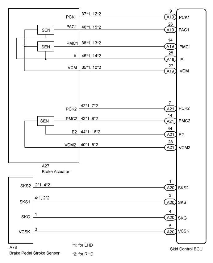
WIRING DIAGRAM
INSPECTION PROCEDURE
Note
When replacing the skid control ECU or brake pedal stroke sensor, perform initialization of linear solenoid valve and calibration Click here.
PROCEDURE
-
CHECK BRAKE PEDAL
-
Check that the brake pedal and the brake pedal stroke sensor are properly installed and that the pedal can be operated normally.
OK The brake pedal is securely installed and can be operated normally -
for LHD:
Check the brake pedal height Click here.
for RHD:
Check the brake pedal height Click here.
OK The pedal height is within the specified range.
NG 
ADJUST BRAKE PEDAL
OK 
-
-
READ VALUE USING INTELLIGENT TESTER (BRAKE PEDAL STROKE SENSOR)
-
Connect the intelligent tester to the DLC3.
-
Turn the engine switch on (IG).
-
Select the Data List mode on the intelligent tester.
Skid control ECU: Tester Display Measurement Item/Range Normal Condition Diagnostic Note Stroke Sensor Stroke sensor /
min.: 0.00 V, max.: 5.00 V
When brake pedal is released:
0.70 to 1.30 V
- Stroke Sensor2 Stroke sensor 2 /
min.: 0.00 V, max.: 5.00 V
When brake pedal is released:
3.70 to 4.30 V
- -
Read the pedal stroke sensor voltage value on the intelligent tester screen.
Result Result Proceed to OK
(The normal condition value is displayed on the intelligent tester)
A for LHD:
NG
B for RHD:
NG
C
B
ADJUST BRAKE PEDAL STROKE SENSOR ASSEMBLY (for LHD) Click here
C
ADJUST BRAKE PEDAL STROKE SENSOR ASSEMBLY (for RHD) Click here
A
-
-
PERFORM INITIALIZATION OF LINEAR SOLENOID VALVE AND CALIBRATION
-
Perform initialization of the linear solenoid valve and calibration Click here.
NEXT
-
-
RECONFIRM DTC
-
Clear the DTCs Click here.
-
Turn the engine switch on (IG).
-
Check if the same DTCs are recorded Click here.
Result Result Proceed to DTCs (C1247/47 and C1392/48) are output A DTCs (C1247/47 and C1392/48) are not output B
B
END
A
-
-
CHECK HARNESS AND CONNECTOR (SKID CONTROL ECU - BRAKE PEDAL STROKE SENSOR)
-
Disconnect the A20 ECU connector.
-
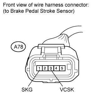
Disconnect the A78 sensor connector.
-
Measure the resistance according to the value(s) in the table below.
Standard resistance for LHD: Tester Connection Condition Specified Condition A20-1 (SKS2) - A78-2 (SKS2) Always Below 1 Ω A20-3 (SKS) - A78-4 (SKS1) Always Below 1 Ω A20-4 (SKG) - A78-1 (SKG) Always Below 1 Ω A20-5 (VCSK) - A78-3 (VCSK) Always Below 1 Ω A20-1 (SKS2) - Body ground Always 10 kΩ or higher A20-3 (SKS) - Body ground Always 10 kΩ or higher A20-4 (SKG) - Body ground Always 10 kΩ or higher A20-5 (VCSK) - Body ground Always 10 kΩ or higher for RHD: Tester Connection Condition Specified Condition A20-1 (SKS2) - A78-4 (SKS2) Always Below 1 Ω A20-3 (SKS) - A78-2 (SKS1) Always Below 1 Ω A20-4 (SKG) - A78-1 (SKG) Always Below 1 Ω A20-5 (VCSK) - A78-3 (VCSK) Always Below 1 Ω A20-1 (SKS2) - Body ground Always 10 kΩ or higher A20-3 (SKS) - Body ground Always 10 kΩ or higher A20-4 (SKG) - Body ground Always 10 kΩ or higher A20-5 (VCSK) - Body ground Always 10 kΩ or higher
NG
REPAIR OR REPLACE HARNESS OR CONNECTOR
OK
-
-
INSPECT SKID CONTROL ECU (SENSOR INPUT VOLTAGE)
-
Reconnect the A20 ECU connector.
-
Disconnect the A78 sensor connector.
-
Turn the engine switch on (IG).
-
Measure the voltage according to the value(s) in the table below.
Standard voltage Tester Connection Switch Condition Specified Condition A78-3 (VCSK) - A78-1 (SKG) Engine switch on (IG) 4.5 to 5.5 V Result Result Proceed to OK A NG (for LHD) B NG (for RHD) C
B
REPLACE SKID CONTROL ECU (for LHD) Click here
C
REPLACE SKID CONTROL ECU (for RHD) Click here
A
-
-
READ VALUE USING INTELLIGENT TESTER (BRAKE PEDAL STROKE SENSOR)
-
Connect the brake pedal effort gauge.
-
Connect the intelligent tester to the DLC3.
-
Turn the engine switch on (IG).
-
Select the Data List mode on the intelligent tester.
Skid control ECU: Tester Display Measurement Item/Range Normal Condition Diagnostic Note Stroke Sensor Stroke sensor /
min.: 0.00 V, max.: 5.00 V
When brake pedal is released:
0.70 to 1.30 V
- Stroke Sensor2 Stroke sensor 2 /
min.: 0.00 V, max.: 5.00 V
When brake pedal is released:
3.70 to 4.30 V
- -
When depressing the brake pedal with the amount of force listed in the table below, check that the output value displayed on the intelligent tester is normal.
Tech Tips
The brake pedal must be depressed gradually.
Standard voltage Brake Effort
N (kgf, lbf)
Stroke Sensor
(Data List)
Stroke Sensor 2
(Data List)
50 (5.1, 11) 1.04 to 1.44 V 3.52 to 3.92 V 100 (10.2, 22) 1.13 to 1.53 V 3.38 to 3.78 V 150 (15.3, 34) 1.27 to 1.67 V 3.29 to 3.69 V 200 (20.4, 45) 1.34 to 1.74 V 3.22 to 3.62 V
NG
REPLACE BRAKE PEDAL STROKE SENSOR ASSEMBLY Click here
OK
-
-
CHECK HARNESS AND CONNECTOR (SKID CONTROL ECU - BRAKE ACTUATOR)
-
Make sure that there is no looseness at the locking parts and the connecting parts of the connectors.
-
Disconnect the A19 and A21 ECU connectors.
-
Disconnect the A27 actuator connector.
-
Measure the resistance according to the value(s) in the table below.
Standard resistance for LHD: Tester Connection Condition Specified Condition A19-27 (VCM) - A27-35 (VCM) Always Below 1 Ω A19-27 (VCM) - Body ground Always 10 kΩ or higher A19-26 (PAC1) - A27-46 (PAC1) Always Below 1 Ω A19-26 (PAC1) - Body ground Always 10 kΩ or higher A19-14 (PMC1) - A27-38 (PMC1) Always Below 1 Ω A19-14 (PMC1) - Body ground Always 10 kΩ or higher A19-28 (E) - A27-45 (E) Always Below 1 Ω A19-28 (E) - Body ground Always 10 kΩ or higher A19-9 (PCK1) - A27-37 (PCK1) Always Below 1 Ω A19-9 (PCK1) - Body ground Always 10 kΩ or higher A21-28 (VCM2) - A27-40 (VCM2) Always Below 1 Ω A21-28 (VCM2) - Body ground Always 10 kΩ or higher A21-14 (PMC2) - A27-43 (PMC2) Always Below 1 Ω A21-14 (PMC2) - Body ground Always 10 kΩ or higher A21-44 (E2) - A27-44 (E2) Always Below 1 Ω A21-44 (E2) - Body ground Always 10 kΩ or higher A21-7 (PCK2) - A27-42 (PCK2) Always Below 1 Ω A21-7 (PCK2) - Body ground Always 10 kΩ or higher for RHD: Tester Connection Condition Specified Condition A19-27 (VCM) - A27-10 (VCM) Always Below 1 Ω A19-27 (VCM) - Body ground Always 10 kΩ or higher A19-26 (PAC1) - A27-15 (PAC1) Always Below 1 Ω A19-26 (PAC1) - Body ground Always 10 kΩ or higher A19-14 (PMC1) - A27-13 (PMC1) Always Below 1 Ω A19-14 (PMC1) - Body ground Always 10 kΩ or higher A19-28 (E) - A27-14 (E) Always Below 1 Ω A19-28 (E) - Body ground Always 10 kΩ or higher A19-9 (PCK1) - A27-12 (PCK1) Always Below 1 Ω A19-9 (PCK1) - Body ground Always 10 kΩ or higher A21-28 (VCM2) - A27-5 (VCM2) Always Below 1 Ω A21-28 (VCM2) - Body ground Always 10 kΩ or higher A21-14 (PMC2) - A27-8 (PMC2) Always Below 1 Ω A21-14 (PMC2) - Body ground Always 10 kΩ or higher A21-44 (E2) - A27-16 (E2) Always Below 1 Ω A21-44 (E2) - Body ground Always 10 kΩ or higher A21-7 (PCK2) - A27-7 (PCK2) Always Below 1 Ω A21-7 (PCK2) - Body ground Always 10 kΩ or higher
NG
REPAIR OR REPLACE HARNESS OR CONNECTOR
OK
-
-
READ VALUE USING INTELLIGENT TESTER (MASTER CYLINDER PRESSURE SENSOR)
-
Reconnect the A19 and A21 ECU connectors and the A27 actuator connector.
-
Connect the intelligent tester to the DLC3.
-
Turn the engine switch on (IG).
-
Select the Data List on the intelligent tester.
Skid control ECU: Tester Display Measurement Item/Range Normal Condition Diagnostic Note Master Cylinder Sensor Master cylinder pressure sensor 1 reading / Min.: 0.00 V, Max.: 5.00 V When brake pedal is released:
0.30 to 0.90 V
Reading increases when brake pedal is depressed Master Cylinder Sensor2 Master cylinder pressure sensor 2 reading / Min.: 0.00 V, Max.: 5.00 V When brake pedal is released:
0.30 to 0.90 V
Reading increases when brake pedal is depressed Electronically Controlled Brake System Solenoid (SMC2) Electronically controlled brake system solenoid (SMC2) / ON or OFF ON: Operates
OFF: Does not operate
- Electronically Controlled Brake System Solenoid (SMC1) Electronically controlled brake system solenoid (SMC1) / ON or OFF ON: Operates
OFF: Does not operate
- -
Check the output value of the master cylinder pressure sensor as the brake pedal is depressed.
OK Output voltage is proportional to pedal stroke, and there is not a large difference in output between sensor 1 and sensor 2. Tech Tips
-
If DTCs are stored due to the brake pedal being depressed, and electronically controlled brake system control is prohibited, check the Freeze Frame Data recorded at the time the DTCs were stored.
-
If the Freeze Frame Data shows that there are no abnormalities in the output of the master cylinder pressure sensors and no difference in the output between sensor 1 and sensor 2, proceed to the next step.
Result Result Proceed to OK A NG (for LHD) B NG (for RHD) C -
B
REPLACE BRAKE ACTUATOR ASSEMBLY (for LHD) Click here
C
REPLACE BRAKE ACTUATOR ASSEMBLY (for RHD) Click here
A
-
-
RECONFIRM DTC
-
Clear the DTC Click here.
-
Perform the road and braking test.
-
Check if the same DTCs are recorded Click here.
Tech Tips
Reinstall the sensors, connectors, etc. and restore the vehicle to its prior condition before rechecking for DTCs.
Result Result Proceed to DTCs (C1247/47 and C1392/48) are not output A DTCs (C1247/47 and C1392/48) are output (for LHD) B DTCs (C1247/47 and C1392/48) are output (for RHD) C
B
REPLACE SKID CONTROL ECU (for LHD) Click here
C
REPLACE SKID CONTROL ECU (for RHD) Click here
A 
END
-