ELECTRONICALLY CONTROLLED BRAKE SYSTEM, Diagnostic DTC:C1235/35, C1236/36, C1238/38, C1239/39, C1275/75, C1276/76, C1277/77, C1278/78

| DTC Code | DTC Name |
|---|---|
| C1235/35 | Foreign Object is Attached on Tip of Front Speed Sensor RH |
| C1236/36 | Foreign Object is Attached on Tip of Front Speed Sensor LH |
| C1238/38 | Foreign Object is Attached on Tip of Rear Speed Sensor RH |
| C1239/39 | Foreign Object is Attached on Tip of Rear Speed Sensor LH |
| C1275/75 | Abnormal Change in Output Signal of Front Speed Sensor RH (Test Mode DTC) |
| C1276/76 | Abnormal Change in Output Signal of Front Speed Sensor LH (Test Mode DTC) |
| C1277/77 | Abnormal Change in Output Signal of Rear Speed Sensor RH (Test Mode DTC) |
| C1278/78 | Abnormal Change in Output Signal of Rear Speed Sensor LH (Test Mode DTC) |
DESCRIPTION
Refer to DTCs C1464/31 and C1465/32 Click here.
DTCs C1275/75 to C1278/78 can be deleted when the speed sensor sends a vehicle speed signal or the Test Mode ends. DTCs C1275/75 to C1278/78 are output only in the Test Mode.
| DTC Code | Information Code | DTC Detection Condition | Trouble Area |
|---|---|---|---|
| C1235/35 | 302 | When either of the following is detected:
|
|
| C1236/36 | 303 | ↑ |
|
| C1238/38 | 304 | ↑ |
|
| C1239/39 | 305 | ↑ |
|
| C1275/75 C1276/76 |
- | Detected only during test mode. |
|
| C1277/77 C1278/78 |
- | Detected only during test mode. |
|
Tech Tips
-
DTC C1235/35 is for the front speed sensor RH.
-
DTC C1236/36 is for the front speed sensor LH.
-
DTC C1238/38 is for the rear speed sensor RH.
-
DTC C1239/39 is for the rear speed sensor LH.
WIRING DIAGRAM
Refer to DTCs C1464/31 and C1465/32 Click here or DTC C1466/33 and C1467/34 Click here.
INSPECTION PROCEDURE
Note
When replacing the skid control ECU, perform initialization of linear solenoid valve and calibration Click here.
PROCEDURE
-
CHECK HARNESS AND CONNECTOR (SKID CONTROL ECU - SPEED SENSOR)
-
Disconnect the A19 and A21 ECU connectors.
-
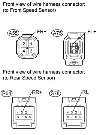
Disconnect the A55 and A75 sensor connectors.
-
Disconnect the R64 and S78 sensor connectors.
-
Measure the resistance according to the value(s) in the table below.
Standard resistance for RH Tester Connection Condition Specified Condition A19-16 (FR+) - A55-2 (FR+) Always Below 1 Ω A19-15 (FR-) - A55-1 (FR-) Always Below 1 Ω A21-11 (RR+) - R64-3 (RR+) Always Below 1 Ω A21-10 (RR-) - R64-4 (RR-) Always Below 1 Ω A19-16 (FR+) - Body ground Always 10 kΩ or higher A19-15 (FR-) - Body ground Always 10 kΩ or higher A21-11 (RR+) - Body ground Always 10 kΩ or higher A21-10 (RR-) - Body ground Always 10 kΩ or higher for LH Tester Connection Condition Specified Condition A21-16 (FL+) - A75-1 (FL+) Always Below 1 Ω A21-15 (FL-) - A75-2 (FL-) Always Below 1 Ω A19-11 (RL+) - S78-3 (RL+) Always Below 1 Ω A19-10 (RL-) - S78-4 (RL-) Always Below 1 Ω A21-16 (FL+) - Body ground Always 10 kΩ or higher A21-15 (FL-) - Body ground Always 10 kΩ or higher A19-11 (RL+) - Body ground Always 10 kΩ or higher A19-10 (RL-) - Body ground Always 10 kΩ or higher
NG 
REPAIR OR REPLACE HARNESS OR CONNECTOR
OK 
-
-
CHECK SKID CONTROL ECU (SENSOR INPUT VOLTAGE)
-
Reconnect the A19 and A21 ECU connectors.
-
Disconnect the A55 sensor connector.
-
Disconnect the A75 sensor connector.
-
Disconnect the R64 sensor connector.
-
Disconnect the S78 sensor connector.
-
Turn the engine switch on (IG).
-
Measure the voltage according to the value(s) in the table below.
Standard voltage Tester Connection Switch Condition Specified Condition A55-2 (FR+) - Body ground Engine switch on (IG) 6.7 to 14 V A75-1 (FL+) - Body ground Engine switch on (IG) 6.7 to 14 V R64-3 (RR+) - Body ground Engine switch on (IG) 6.7 to 14 V S78-3 (RL+)- Body ground Engine switch on (IG) 6.7 to 14 V Result Result Proceed to OK A NG (for LHD) B NG (for RHD) C
B
REPLACE SKID CONTROL ECU (for LHD) Click here
C
REPLACE SKID CONTROL ECU (for RHD) Click here
A
-
-
RECONFIRM DTC
-
Clear the DTC Click here.
-
Start the engine.
-
Drive the vehicle at the speed of 20 km/h (12 mph) or more for 60 seconds or more.
-
Check if the same DTCs are recorded Click here.
Tech Tips
Reinstall the sensors, connectors, etc. and restore the vehicle to its prior condition before rechecking for DTCs.
Result Result Proceed to DTCs (C1238/38, C1239/39) are output A DTCs (C1235/35 and C1236/36) are output (for AWD) A DTCs (C1235/35 and C1236/36) are output (for 2WD) B DTCs (C1235/35, C1236/36, C1238/38 and C1239/39) are not output C
B 
REPLACE FRONT AXLE HUB SUB-ASSEMBLY Click here
C
CHECK FOR INTERMITTENT PROBLEMS Click here
A
-
-
INSPECT SPEED SENSOR TIP
-
Remove the front speed sensor Click here and rear speed sensor Click here.
-
Check the sensor tip.
OK No scratches or foreign matter on the sensor tip. Note
Check the speed sensor signal after replacement Click here.
NG
CLEAN OR REPLACE SPEED SENSOR
OK
-
-
INSPECT SPEED SENSOR ROTOR
-
Remove the front speed sensor rotor Click here.
-
Remove the rear speed sensor rotor Click here.
-
Check the each sensor rotor.
OK No scratches, oil, or foreign matter on the rotors. Note
Check the speed sensor signal after cleaning/replacement Click here.
OK
RECONFIRM DTC Click here
NG 
CLEAN OR REPLACE SPEED SENSOR ROTOR
-
-
REPLACE FRONT AXLE HUB SUB-ASSEMBLY
-
Replace the front axle hub sub-assembly Click here.
Tech Tips
The front speed sensor and front speed sensor rotor are built into the front axle hub sub-assembly.
NEXT
-
-
RECONFIRM DTC
-
Clear the DTCs Click here.
-
Turn the engine switch on (IG).
-
Check if the same DTCs are recorded Click here.
Result Result Proceed to DTCs C1235/35, C1236/36, C1238/38 and C1239/39 are not output A DTCs C1235/35, C1236/36, C1238/38 and C1239/39 are output (for LHD) B DTCs C1235/35, C1236/36, C1238/38 and C1239/39 are output (for RHD) C
B
REPLACE SKID CONTROL ECU (for LHD) Click here
C
REPLACE SKID CONTROL ECU (for RHD) Click here
A
CHECK FOR INTERMITTENT PROBLEMS Click here
-