REAR STABILIZER BAR REMOVAL

-
DISCONNECT NO. 1 ACTUATOR HARNESS CLAMP
-
REMOVE PROPELLER WITH CENTER BEARING SHAFT ASSEMBLY
-
REMOVE REAR WHEEL
-
REMOVE NO. 6 ROCKER PANEL MOULDING PROTECTOR
-
Remove the protector for 1UR-FSE Click here.
-
Remove the protector for 1UR-FE Click here.
-
-
REMOVE NO. 5 ROCKER PANEL MOULDING PROTECTOR
-
Remove the protector for 1UR-FSE Click here.
-
Remove the protector for 1UR-FE Click here.
-
-
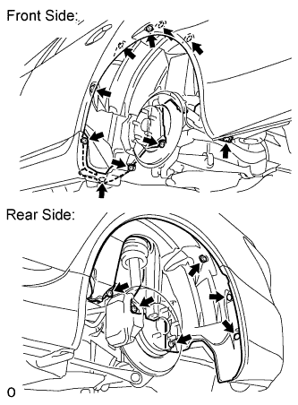
REMOVE REAR WHEEL HOUSE LINER LH
-
Remove the 3 screws, 11 nuts and 2 clips from the liner.
-
-
REMOVE REAR WHEEL HOUSE LINER RH
Tech Tips
Use the same procedures described for the LH side.
-
REMOVE REAR SPEED SENSOR LH
-
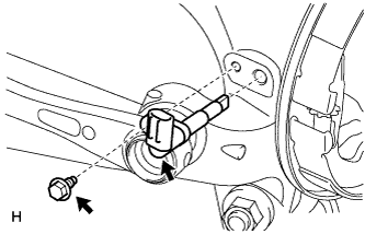
Remove the bolt and sensor.
Note
-
The rear speed sensor is easily damaged. When pulling out the rear speed sensor from the rear axle hub RH, do not use excessive force to rotate and remove it.
-
Prevent foreign matter from attaching to the sensor tip.
-
Do not drop the sensor. If the sensor has been dropped, replace the sensor with a new one.
-
-
-
REMOVE REAR SPEED SENSOR RH
Tech Tips
Use the same procedures described for the LH side.
-
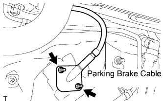
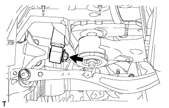
REMOVE PARKING BRAKE CABLE
-
Remove the 2 nuts and disconnect the cable from the vehicle side.
-
-
REMOVE REAR DISC BRAKE CALIPER ASSEMBLY LH
-
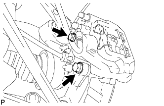
Remove the 2 bolts and disconnect the rear disc brake caliper assembly.
Note
-
Hang the caliper with wire or equivalent.
-
Do not damage the brake hose.
-
-
-
REMOVE REAR DISC BRAKE CALIPER ASSEMBLY RH
Tech Tips
Use the same procedures described for the LH side.
-
REMOVE REAR STABILIZER LINK ASSEMBLY LH
-
Remove the nut and disconnect the stabilizer link from stabilizer bar.
-
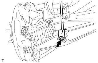
Remove the bolt, nut and stabilizer link from the rear No. 2 suspension arm.
-
-
REMOVE REAR STABILIZER LINK ASSEMBLY RH
Tech Tips
Use the same procedures described for the LH side.
-
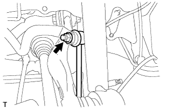
DISCONNECT REAR SHOCK ABSORBER ASSEMBLY LH (w/o Air Suspension)
-
Remove the nut and disconnect the shock absorber from axle carrier side.
-
-
DISCONNECT REAR SHOCK ABSORBER ASSEMBLY RH
Tech Tips
Use the same procedures described for the LH side.
-
DISCONNECT PNEUMATIC CYLINDER WITH REAR SHOCK ABSORBER ASSEMBLY LH (w/ Air Suspension)
-
Remove the nut and disconnect the pneumatic cylinder from axle carrier side.
-
-
DISCONNECT PNEUMATIC CYLINDER WITH REAR SHOCK ABSORBER ASSEMBLY RH
Tech Tips
Use the same procedures described for the LH side.
-
REMOVE REAR SUSPENSION MEMBER SUB-ASSEMBLY
-
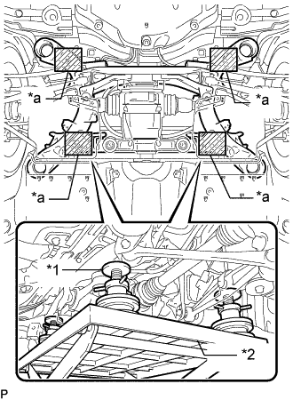
Text in Illustration *1 Attachment *2 Engine Lifter *a Attachment placement location Support the rear suspension member sub-assembly with an engine lifter using 4 attachments or equivalent tools as shown in the illustration.
Note
-
Use the attachments to keep the rear suspension member sub-assembly level.
-
The rear suspension member sub-assembly is a heavy component. Make sure that it is supported securely.
-
-
for Sports Package:
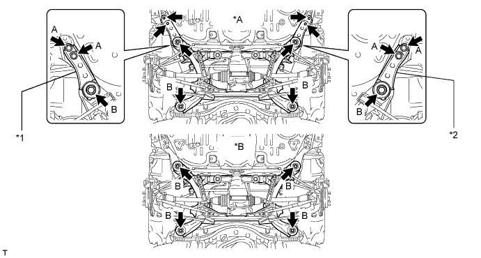
Text in Illustration *A for Sports Package *B for Standard *1 Suspension Member Stopper Lower RH *2 Suspension Member Stopper Lower LH
-
Remove the 4 bolts labeled A.
-
Remove the 4 bolts labeled B and 2 suspension member stoppers.
-
Slowly lower the rear suspension member subassembly.
Note
When lowering the rear suspension member sub-assembly, be careful not to damage the vehicle body or other components installed on the vehicle.
-
-
for Standard:
-
Remove the 4 bolts.
-
Slowly lower the rear suspension member subassembly.
Note
When lowering the rear suspension member sub-assembly, be careful not to damage the vehicle body or other components installed on the vehicle.
-
-
-
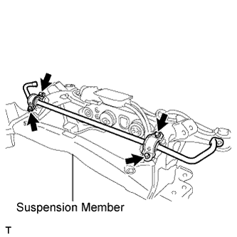
REMOVE REAR STABILIZER BAR
-
Remove the 4 bolts and stabilizer bar from the suspension member.
Tech Tips
The stabilizer bracket and bush are built onto the stabilizer bar. If the bracket and/or bush detach from the bar, replace the bar.
-