FRONT LOWER BALL JOINT (for AWD) INSTALLATION

Tech Tips
-
Use the same procedures for the RH side and LH side.
-
The procedures listed below are for the LH side.
-
A bolt without a torque specification is shown in the standard bolt chart Click here.
-
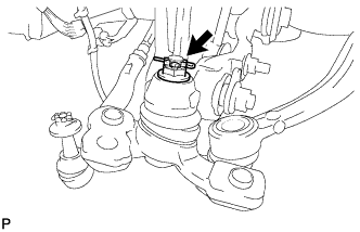
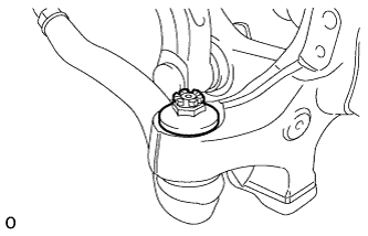
INSTALL FRONT LOWER BALL JOINT ASSEMBLY LH
-
Install the front lower ball joint LH to the front suspension lower arm with the nut.
- Torque:
- 145 N*m { 1479 kgf*cm, 107 ft.*lbf }
Note
If it is necessary to align the holes for the clips after installing the nuts, the nuts can be tightened up to 60° more.
-
Install a new clip.
-
-
INSTALL STEERING KNUCKLE SUB-ASSEMBLY LH
-
Connect the splines of the steering knuckle LH and drive shaft assembly.
-
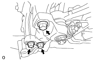
Install the steering knuckle to the front lower ball joint with the 3 bolts.
- Torque:
- 113 N*m { 1149 kgf*cm, 83 ft.*lbf }
-
-
CONNECT FRONT NO. 1 SUSPENSION UPPER ARM ASSEMBLY LH
-
Install the steering knuckle to the front No. 1 suspension upper arm with the nut.
- Torque:
- 60 N*m { 612 kgf*cm, 44 ft.*lbf }
-
Install new clips.
Note
If it is necessary to align the holes for the clips after installing the nuts, the nuts can be tightened up to 60° more.
-
-
CONNECT FRONT NO. 2 SUSPENSION UPPER ARM ASSEMBLY LH
-
Install the steering knuckle to the front No. 2 suspension upper arm with the nut.
- Torque:
- 60 N*m { 612 kgf*cm, 44 ft.*lbf }
-
Install new clips.
Note
If it is necessary to align the holes for the clips after installing the nuts, the nuts can be tightened up to 60° more.
-
-
CONNECT TIE ROD ASSEMBLY LH
-
Connect the tie rod to the steering knuckle with the nut.
- Torque:
- 60 N*m { 612 kgf*cm, 44 ft.*lbf }
-
Install new clips.
Note
If it is necessary to align the holes for the clips after installing the nuts, the nuts can be tightened up to 60° more.
-
-
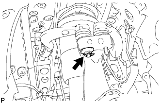
INSTALL FRONT SPEED SENSOR LH
-
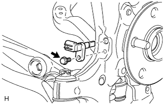
Install the speed sensor to the steering knuckle with the bolt.
- Torque:
- 8.5 N*m { 87 kgf*cm, 75 in.*lbf }
Note
-
Do not damage the tip of the speed sensor.
-
Do not allow foreign matter to contact the tip or installation area of the speed sensor.
-
-
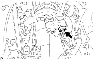
CONNECT SKID CONTROL SENSOR WIRE
-
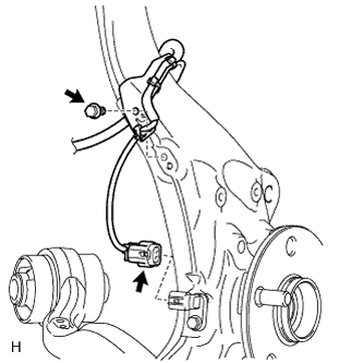
Connect the front speed sensor connector.
-
Install the sensor clamp to the steering knuckle LH with the bolt.
- Torque:
- 8.5 N*m { 87 kgf*cm, 75 in.*lbf }
Note
Do not twist the skid control sensor wire.
-
-
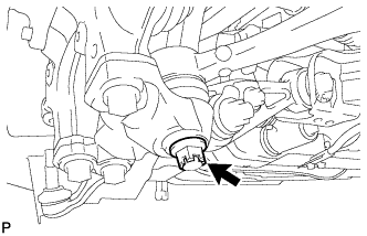
CONNECT FRONT NO. 2 SUSPENSION LOWER ARM LH
-
Connect the front suspension lower arm LH to the front lower ball joint with the nut.
- Torque:
- 145 N*m { 1479 kgf*cm, 107 ft.*lbf }
Note
If it is necessary to align the holes for the clips after installing the nuts, the nuts can be tightened up to 60° more.
-
Install a new clip.
-
-
CONNECT FRONT HEIGHT CONTROL SENSOR SUB-ASSEMBLY LH
-
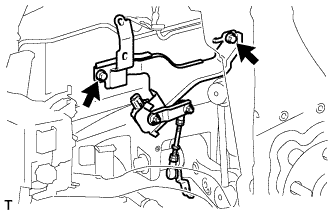
Install the height control sensor with the 2 bolts.
- Torque:
- 14 N*m { 138 kgf*cm, 10 ft.*lbf }
Note
Do not drop the height control sensor. If it is dropped, replace it with a new one.
-
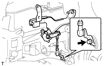
Connect the height control sensor link to the lower arm with the bolt.
- Torque:
- 5.4 N*m { 55 kgf*cm, 48 in.*lbf }
-
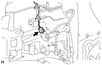
Connect the connector and attach the 2 clips.
-
-
INSTALL FRONT DISC BRAKE DUST COVER LH
-
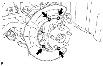
Install the front disc brake dust cover with the 4 bolts.
- Torque:
- 8.0 N*m { 82 kgf*cm, 71 in.*lbf }
-
-
INSTALL FRONT DISC
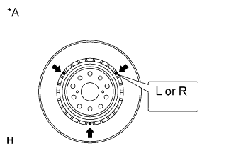
Text in Illustration *A for 18 inch Disc Note
The 18 inch disc has an identification mark. Make sure of the identification mark when installing the disc.
Item Identification mark 18 inch disc LH L 18 inch disc RH R Tech Tips
The 17 inch disc has no identification mark. The disc can be installed to the LH or RH side.
-
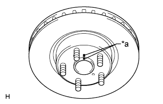
Text in Illustration *a Matchmark Align the matchmarks, and install the front disc.
Tech Tips
When replacing the front disc with a new one, select the installation position where the front disc has the minimum runout.
-
-
INSTALL FRONT DISC BRAKE CALIPER ASSEMBLY LH
-
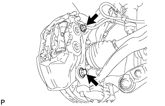
Install the front disc brake caliper to the steering knuckle with 2 new bolts.
- Torque:
- 135 N*m { 1377 kgf*cm, 100 ft.*lbf }
Note
-
Do not twist the flexible hose.
-
Make sure the threaded parts are free from foreign matter and are not damaged.
-
Be careful not to overtighten the bolts, as the steering knuckle is made of aluminum.
-
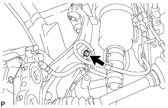
Connect the flexible hose to the steering knuckle with the bolt.
- Torque:
- 20 N*m { 204 kgf*cm, 15 ft.*lbf }
-
-
INSTALL FRONT AXLE SHAFT NUT LH
-
Clean the threaded parts on the drive shaft and axle shaft nut using a non-residue solvent.
Note
-
Be sure to perform this work for a new drive shaft.
-
Keep the threaded parts free of oil and foreign objects.
-
-
Using a 30 mm socket wrench, install a new axle shaft nut.
- Torque:
- 294 N*m { 2998 kgf*cm, 217 ft.*lbf }
Note
Do not stake the shaft nut.
Tech Tips
Stake the shaft nut after the axle hub bearing looseness and axle hub runout inspections.
-
-
INSTALL FRONT WHEEL
- Torque:
- 140 N*m { 1428 kgf*cm, 103 ft.*lbf }
-
INSPECT AND ADJUST FRONT WHEEL ALIGNMENT
-
Inspect and adjust the front wheel alignment Click here.
-
-
CHECK SUSPENSION CONTROL SYSTEM
-
Check the suspension control system Click here.
-
-
ADJUST HEADLIGHT ASSEMBLY
-
Adjust the headlight assembly Click here.
-
-
ADJUST OBJECT RECOGNITION CAMERA
-
Adjust the object recognition camera Click here.
-