FRONT SUSPENSION MEMBER (for AWD) REMOVAL

-
REMOVE ENGINE AND TRANSMISSION
-
REMOVE FRONT FRAME ASSEMBLY
-
Remove the 4 nuts and front frame assembly.
-
-
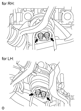
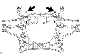
REMOVE FRONT ENGINE MOUNTING INSULATOR
-
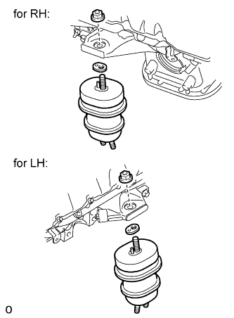
Remove the 2 nuts, 2 engine mounting spacers and 2 front engine mounting insulators.
-
-
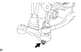
REMOVE FRONT STABILIZER LINK ASSEMBLY LH
-
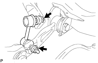
Remove the 2 nuts and front stabilizer link.
Tech Tips
If the ball joint turns together with the nut, use a 6 mm hexagon wrench to hold the stud.
-
-
REMOVE FRONT STABILIZER LINK ASSEMBLY RH
Tech Tips
Use the same procedure described for the LH side.
-
REMOVE FRONT NO. 1 STABILIZER BRACKET LH
-
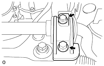
Remove the 2 bolts and front No. 1 stabilizer bracket LH from the front frame assembly.
-
-
REMOVE FRONT NO. 1 STABILIZER BRACKET RH
Tech Tips
Use the same procedure described for the LH side.
-
REMOVE FRONT STABILIZER BAR
-
Remove the front stabilizer bar from the vehicle.
-
-
REMOVE FRONT SUSPENSION MEMBER BRACKET SUB-ASSEMBLY LH
-
Remove the 4 bolts and bracket.
-
-
REMOVE FRONT SUSPENSION MEMBER BRACKET SUB-ASSEMBLY RH
-
Remove the 4 bolts and bracket.
-
-
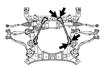
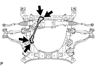
REMOVE POWER STEERING LINK ASSEMBLY
-
Remove the 2 bolts, 2 nuts, 2 washers and power steering link from the front frame.
-
-
REMOVE FRONT NO. 2 SUSPENSION LOWER ARM LH
-
Remove the clip and nut.
-
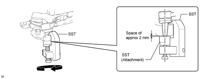
Install SST (attachment) to the front No. 2 suspension lower arm assembly LH so that there is a space of approximately 2 mm (0.0787 in.) between the front No. 2 suspension lower arm and attachment.
- SST
- 09628-50010 ( 09628-05010 )
Note
As SST may become damaged, make sure the space between the front No. 2 suspension lower arm and attachment is not less than 2 mm (0.0787 in.).
-
Using SST, remove the front No. 2 suspension lower arm from the front lower ball joint.
- SST
- 09628-50010 ( 09628-05010 )
Note
-
Apply molybdenum grease to the threads and end of the SST bolt.
-
Do not damage the dust cover of the front No. 2 lower arm.
-
Make sure that the bolt of SST and the front No. 2 suspension lower arm LH are in a straight line when installing SST.
-
Do not apply a torque of 160 N*m (1631 kgf*cm, 118 ft.*lbf) or more to SST as it may be damaged.
-
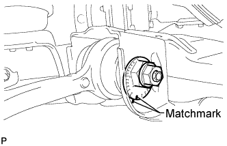
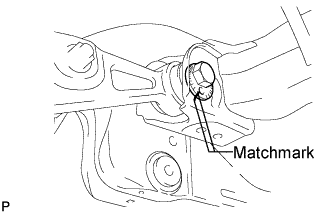
Put matchmarks on the front suspension toe adjusting cam and front frame assembly.
-
Put matchmarks on the front suspension No. 2 toe adjusting plate and front frame assembly.
-
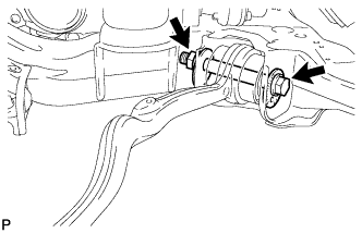
Remove the nut, front suspension No. 2 toe adjusting plate and bolt.
-
Remove the front suspension toe adjusting cam and the front suspension lower arm LH.
-
-
REMOVE FRONT NO. 2 SUSPENSION LOWER ARM RH
Tech Tips
Use the same procedure described for the LH side.
-
REMOVE LOWER FRONT SHOCK ABSORBER BRACKET SUB-ASSEMBLY LH
-
Remove the nut and front shock absorber upper bracket plate, and disconnect the front shock absorber lower bracket from the front suspension lower arm LH.
-
-
REMOVE LOWER FRONT SHOCK ABSORBER BRACKET SUB-ASSEMBLY RH
Tech Tips
Use the same procedure described for the LH side.
-
REMOVE FRONT SUSPENSION LOWER ARM ASSEMBLY LH
-
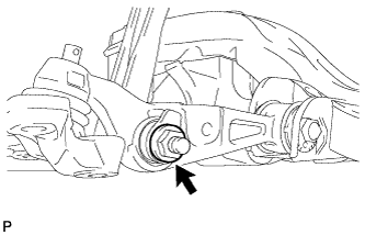
Put matchmarks on the camber adjusting cam and front frame assembly.
-
Put matchmarks on the No. 2 camber adjusting cam and front frame assembly.
-
Remove the nut and No. 2 camber adjusting cam.
-
Remove the camber adjusting cam and front suspension lower arm LH.
-
-
REMOVE FRONT SUSPENSION LOWER ARM ASSEMBLY RH
Tech Tips
Use the same procedure described for the LH side.