FRONT SHOCK ABSORBER (w/ Air Suspension) REMOVAL

Note
Be sure to read the ''PRECAUTION'' thoroughly before servicing Click here.
Tech Tips
-
Use the same procedures for the RH side and LH side.
-
The procedures listed below are for the LH side.
-
REMOVE COWL TOP VENTILATOR LOUVER
-

for LHD:
Remove the 6 clips and cowl top ventilator louver RH.
-

for RHD:
Remove the 6 clips and cowl top ventilator louver LH.
-
-
PRECAUTION
Note
After turning the engine switch off, waiting time may be required before disconnecting the cable from the battery terminal. Therefore, make sure to read the disconnecting the cable from the battery terminal notice before proceeding with work Click here.
-
DISCONNECT CABLE FROM NEGATIVE BATTERY TERMINAL
Note
When disconnecting the cable, some systems need to be initialized after the cable is reconnected Click here.
-
REMOVE FRONT WHEEL
-
REMOVE FRONT AXLE SHAFT NUT LH (for AWD)
-
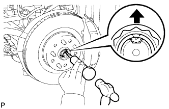
Using SST and a hammer, release the staked part of the front axle shaft nut.
- SST
- 09930-00010
Note
Release the staked part of the nut completely, otherwise the threads of the drive shaft may be damaged.
-
-
DISCONNECT SPEED SENSOR CONNECTOR (for 2WD)
-
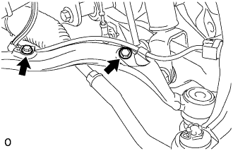
Remove the 2 bolts and disconnect the connector from the speed sensor.
Note
Do not twist the speed sensor wire.
-
-
DISCONNECT FRONT DISC BRAKE CALIPER ASSEMBLY LH
-
Remove the bolt and disconnect the flexible hose from the steering knuckle.
-
Remove the 2 bolts and front disc brake caliper assembly LH.
Note
-
Hang the front disc brake caliper assembly with a rope or wire.
-
Do not damage the brake hose.
-
-
-
REMOVE FRONT DISC
-
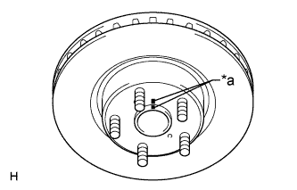
Text in Illustration *a Matchmark Put matchmarks on the front disc and the axle hub if planning to reuse the disc.
-
Remove the front disc.
-
-
REMOVE FRONT DISC BRAKE DUST COVER LH
-
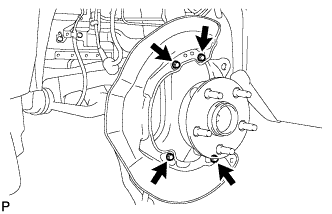
Remove the 4 bolts and front disc brake dust cover LH.
-
-
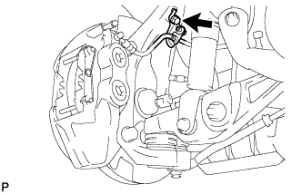
DISCONNECT SKID CONTROL SENSOR WIRE (for AWD)
-
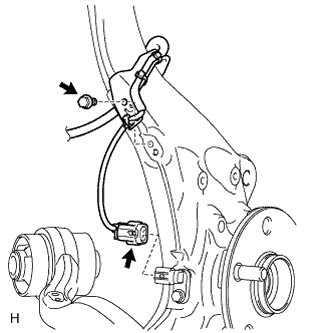
Disconnect the front speed sensor connector.
Note
Do not twist the skid control sensor wire.
-
Remove the bolt and sensor clamp.
-
-
REMOVE FRONT SPEED SENSOR LH (for AWD)
-
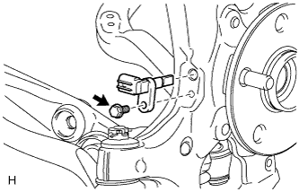
Remove the bolt and speed sensor from the steering knuckle.
Note
-
Do not damage the tip of the speed sensor.
-
Do not allow foreign matter to contact the tip or installation area of the speed sensor.
-
-
-
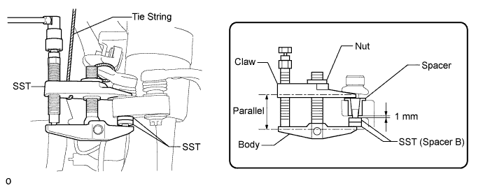
DISCONNECT TIE ROD ASSEMBLY LH
-
Remove the clip and nut.
-
Install 2 spacers (SST spacer B) onto the tie rod assembly LH so that there is a space of approximately 1 mm (0.0397 in.) between the arm and spacers.
- SST
- 09960-20010 ( 09961-02060 )
Note
-
Make sure to install the spacers (SST spacer B) as the steering knuckle spacer may shift.
-
As SST may become damaged, make sure the space between the arm and spacers is not 1 mm (0.0397 in.) or less.
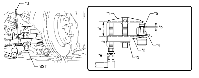
Text in Illustration *1 Body *2 Claw *3 Nut *4 Spacer B *a Parallel *b 1 mm (0.0397 in.) *c Molybdenum Grease Application Area *d String *e Place the wrench here - - Note
-
Do not damage the dust cover.
-
As the dust cover may be damaged, adjust SST with the center nut so that the body and crow are the parallel.
-
Make sure to tie the string of SST to the vehicle to prevent SST from dropping.
-
Using SST, disconnect the tie rod assembly from the steering knuckle.
- SST
- 09960-20010 ( 09961-02010 )
-
-
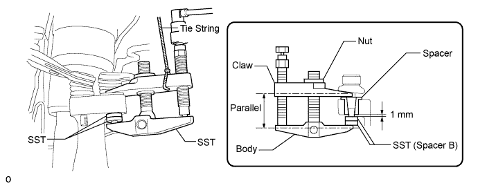
DISCONNECT FRONT NO. 1 SUSPENSION UPPER ARM ASSEMBLY LH (for AWD)
-
Remove the clip and nut.
-
Install 2 spacers (SST spacer B) onto the front No. 1 suspension upper arm assembly LH so that there is a space of approximately 1 mm (0.0394 in.) between the arm and spacers.
- SST
- 09960-20010 ( 09961-02060 )
Note
-
Make sure to install the spacers (SST spacer B) as the steering knuckle spacer may shift.
-
As SST may become damaged, make sure the space between the arm and spacers is not less than 1 mm (0.0394 in.).
-
Using SST, disconnect the front No. 1 suspension upper arm from the steering knuckle.
- SST
- 09960-20010 ( 09961-02010 )
Note
-
Apply molybdenum grease to the threads and end of the SST bolt.
-
Do not damage the dust cover.
-
As the dust cover may be damaged, adjust SST with the center nut so that the body and claw are parallel.
-
Make sure to tie the string of SST to the vehicle to prevent SST from dropping.
-
-
DISCONNECT FRONT NO. 2 SUSPENSION UPPER ARM ASSEMBLY LH (for AWD)
-
Remove the clip and nut.
-
Install 2 spacers (SST spacer B) onto the front No. 2 suspension upper arm assembly LH so that there is a space of approximately 1 mm (0.0394 in.) between the arm and spacers.
- SST
- 09960-20010 ( 09961-02060 )
Note
-
Make sure to install the spacers (SST spacer B) as the steering knuckle spacer may shift.
-
As SST may become damaged, make sure the space between the arm and spacers is not less than 1 mm (0.0394 in.).
-
Using SST, disconnect the front No. 2 suspension upper arm from the steering knuckle.
- SST
- 09960-20010 ( 09961-02010 )
Note
-
Apply molybdenum grease to the threads and end of the SST bolt.
-
Do not damage the dust cover.
-
As the dust cover may be damaged, adjust SST with the center nut so that the body and claw are parallel.
-
Make sure to tie the string of SST to the vehicle to prevent SST from dropping.
-
-
REMOVE STEERING KNUCKLE SUB-ASSEMBLY LH (for AWD)
-
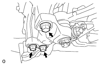
Remove the 3 bolts. Then disconnect the steering knuckle from the front lower ball joint.
-
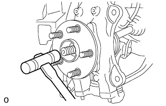
Using a plastic-faced hammer, lightly tap the end of the front drive shaft to remove the front axle hub and steering knuckle from the front drive shaft.
Tech Tips
If the spline connection is tight, using a brass bar and hammer, tap the front drive shaft.
-
While supporting the drive shaft, remove the steering knuckle LH.
Note
-
Do not damage the drive shaft outboard joint boot.
-
Suspend the drive shaft assembly with a rope or wire.
-
Be careful when handling or installing the drive shaft as bending or sliding the drive shaft excessively may cause the tripod joint to come out of its groove.
-
-
-
DISCONNECT FRONT NO. 1 SUSPENSION LOWER ARM ASSEMBLY LH (for 2WD)
-
Remove the clip and nut.
-
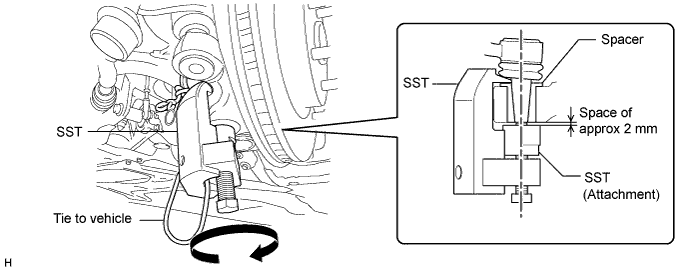
Install SST (attachment) to the front No. 1 suspension lower arm assembly LH so that there is a space of approximately 2 mm (0.0787 in.) between the arm and attachment.
- SST
- 09628-50010 ( 09628-05010 )
Note
-
Be sure to install SST (attachment) as the spacer may shift.
-
As SST may become damaged, make sure the space between the arm and attachment is not less than 2 mm (0.0787 in.).
-
Using SST, disconnect the front No. 1 suspension lower arm assembly LH from the steering knuckle.
- SST
- 09628-50010 ( 09628-05010 )
Note
-
Apply molybdenum grease to the bolt threads and end of the SST bolt.
-
Do not damage the dust cover of the lower arm No. 1.
-
Make sure that the bolt of SST and the ball joint are in a straight line when installing SST.
-
Be sure to tie the string of SST to the vehicle, to prevent SST from dropping.
-
Do not apply a torque of 160 N*m (1631 kgf*cm, 118 ft.*lbf) or more to SST as it may be damaged.
-
-
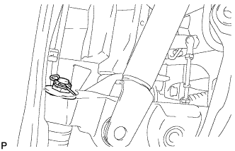
DISCONNECT FRONT HEIGHT CONTROL SENSOR SUB-ASSEMBLY LH (for 2WD)
-
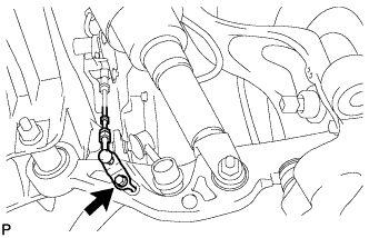
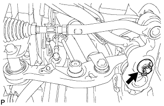
Remove the bolt, and then remove the bracket of the front height control sensor LH.
-
-
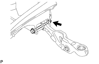
DISCONNECT FRONT HEIGHT CONTROL SENSOR SUB-ASSEMBLY LH (for AWD)
-
Remove the nut, and then remove the bracket of the front height control sensor LH.
-
-
REMOVE FRONT STABILIZER LINK ASSEMBLY LH (for 2WD)
-
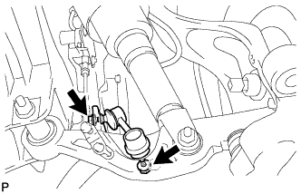
Remove the 2 nuts and front stabilizer link.
Tech Tips
If the ball joint turns together with the nut, use a 6 mm hexagon wrench to hold the stud.
-
-
REMOVE FRONT STABILIZER LINK ASSEMBLY LH (for AWD)
-
Remove the 2 nuts and front stabilizer link.
Tech Tips
If the ball joint turns together with the nut, use a 6 mm hexagon wrench to hold the stud bolt.
-
-
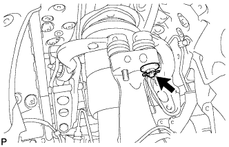
REMOVE AIR CONNECTOR CLIP HOLDER
-
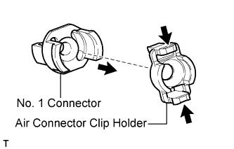
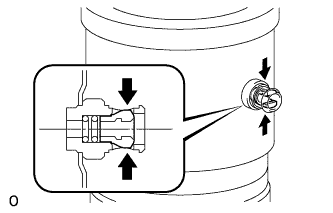
Pinch and pull the air connector clip holder to release the connector No. 1.
-
-
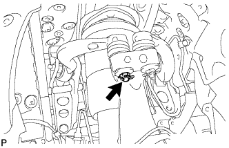
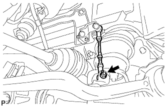
DISCONNECT NO. 4 HEIGHT CONTROL TUBE
-
Pinch and pull the connector No. 1 to release it.
-
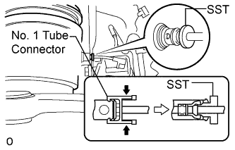
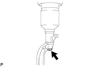
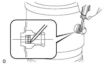
Using SST, disconnect the No. 4 height control tube from the pneumatic cylinder with front shock absorber assembly LH.
- SST
- 09730-00010
Note
After pulling out the height control tube, replace the O-ring and plate with new ones.
-
-
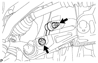
DISCONNECT FRONT NO. 2 SUSPENSION LOWER ARM ASSEMBLY LH (for 2WD)
-
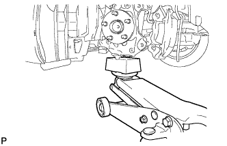
Support the steering knuckle LH with a jack and wooden block.
-
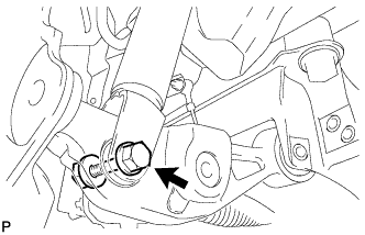
Remove the bolt and nut, and then disconnect the bottom side of the pneumatic cylinder with front shock absorber assembly LH from the front No. 2 suspension lower arm LH.
-
Remove the nut and clip.
-
Install SST (attachment) to the front No. 2 suspension lower arm assembly LH so that there is a space of approximately 2 mm (0.0787 in.) between the front No. 2 suspension lower arm and attachment.
- SST
- 09628-50010 ( 09628-05010 )
Note
-
Make sure to install SST (attachment) as the spacer may shift.
-
As SST may become damaged, make sure the space between the front No. 2 suspension lower arm and attachment is not less than 2 mm (0.0787 in.).
-
Using SST, disconnect the front No. 2 suspension lower arm assembly LH from the lower ball joint.
- SST
- 09628-50010 ( 09628-05010 )

Tech Tips
When installing SST, insert SST from the rear of the vehicle, place it on the lower arm and rotate it so that it is as shown in the illustration.
Note
-
Apply molybdenum grease to the bolt threads and end of the SST bolt.
-
Do not damage the dust cover.
-
Make sure that the bolt of SST and the ball joint are in a straight line when installing SST.
-
Be sure to tie the string of SST to the vehicle to prevent SST from dropping.
-
Do not apply a torque of 160 N*m (1631 kgf*cm, 118 ft.*lbf) or more to SST as it may be damaged.
-
Loosen the nut of the No. 2 suspension lower arm.
-
-
REMOVE AIR CLEANER INLET COVER SUB-ASSEMBLY (for 2WD)
-
Remove the 4 clips and air cleaner inlet cover.
-
-
REMOVE AIR CLEANER INLET COVER SUB-ASSEMBLY (for AWD)
-
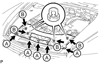
Remove the 5 clips labeled A.
-
Lift up the air cleaner inlet cover sub-assembly to detach the 4 clips labeled B, and remove the air cleaner inlet cover sub-assembly.
-
-
REMOVE ENGINE ROOM SIDE COVER LH (for 2WD)
-
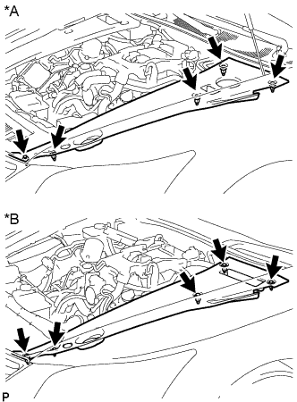
Text in Illustration *A for LHD *B for RHD Remove the 5 clips and engine room side cover LH.
-
-
REMOVE ENGINE ROOM SIDE COVER LH (for AWD)
-
Text in Illustration *A for LHD *B for RHD Remove the 5 clips and engine room side cover LH.
-
-
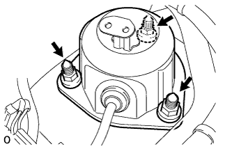
REMOVE FRONT SHOCK ABSORBER CAP LH (for 2WD)
-
Remove the 3 nuts and front shock absorber cap LH.
-
Disconnect the connector.
-
-
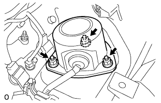
REMOVE FRONT SHOCK ABSORBER CAP LH (for AWD)
-
Remove the 3 nuts and front shock absorber cap LH.
-
Disconnect the connector.
-
-
REMOVE ABSORBER CONTROL ACTUATOR
-
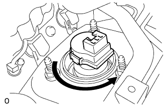
Turn the absorber control actuator counterclockwise 40° and remove it from the pneumatic cylinder with front shock absorber assembly LH.
-
-
REMOVE PNEUMATIC CYLINDER WITH FRONT SHOCK ABSORBER ASSEMBLY LH (for 2WD)
-
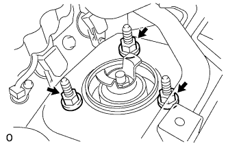
Remove the 3 nuts and pneumatic cylinder with front shock absorber assembly LH.
Note
Hold the pneumatic cylinder with front shock absorber assembly LH to prevent it from dropping.
-
-
REMOVE PNEUMATIC CYLINDER WITH FRONT SHOCK ABSORBER ASSEMBLY LH (for AWD)
-
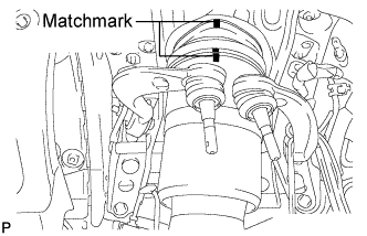
When reusing the pneumatic cylinder with front shock absorber assembly LH:
Place matchmarks on the front suspension support assembly and pneumatic cylinder chamber.
-
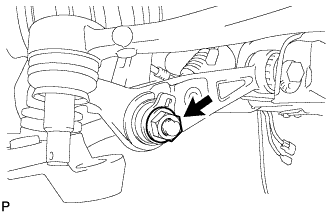
Remove the nut and upper front shock absorber bracket plate, and disconnect the lower front shock absorber bracket sub-assembly LH from the front No. 1 suspension lower arm LH.
-
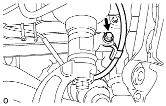
Remove the bolt, and disconnect the skid control sensor wire from the pneumatic cylinder with front shock absorber assembly LH.
-
Remove the 3 nuts and pneumatic cylinder with front shock absorber assembly LH.
Note
Hold the pneumatic cylinder with front shock absorber assembly LH to prevent it from dropping.
-
-
REMOVE LOWER FRONT SHOCK ABSORBER BRACKET SUB-ASSEMBLY LH (for AWD)
-
Remove the bolt and lower front shock absorber bracket sub-assembly LH.
-
-
REMOVE FRONT PNEUMATIC CYLINDER LH O-RING
Tech Tips
If replacing the pneumatic cylinder with front shock absorber assembly LH with a new one, this procedure is not necessary.
-
Using a screwdriver, detach the 2 clips and remove the tube connector.
-
Using a screwdriver, remove the plate and 2 O-rings.
-