FRONT WHEEL ALIGNMENT (for AWD) ADJUSTMENT

Note
-
When the wheel alignment is performed, or a suspension related part is removed and installed/replaced, make sure to the cable from the negative (-) battery terminal for 2 seconds or more after finishing, and then reconnect the cable and perform initialization.
-
If the vehicle is equipped with a VSC system, when the wheel alignment is performed, or a suspension related part is removed and installed/replaced, always perform the following initialization so that the system can function normally: (1) Disconnect the cable from the negative (-) battery terminal for 2 seconds or more and then reconnect it; then (2) perform the yaw rate sensor zero point calibration and test mode inspection.
-
If the vehicle has an object recognition camera, after the wheel alignment is performed, always adjust the object recognition camera.
-
ADJUST FRONT SUSPENSION MEMBER
-
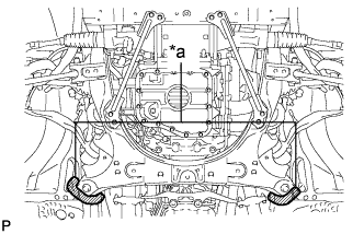
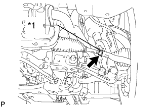
Text in Illustration *a Spray Area Before removing the front suspension member, place matchmarks on the front suspension member and vehicle body with marking spray.
Tech Tips
Spray from the rear of the vehicle.
-
When installing the front suspension member, align the matchmarks on the front suspension member and vehicle body, and then install the front suspension member.
-
-
INSPECT TIRES
-
Check the tires for wear and proper inflation pressure.
Standard Cold Tire Inflation Pressure (for Europe) Tire Size Front
kPa (kgf/cm2, psi)
Rear
kPa (kgf/cm2, psi)
235/50R18 97W 330 (3.3, 48)*1 330 (3.3, 48)*1 280 (2.8, 41)*2 280 (2.8, 41)*2 250 (2.5, 36)*3 240 (2.4, 35)*3 245/45R19 98Y 280 (2.8, 41)*1 300 (3.0, 44)*1 250 (2.5, 36)*2 270 (2.7, 39)*2 240 (2.4, 35)*3 240 (2.4, 35)*3 *1: For driving at over 210 km/h (131 mph)
*2: For driving at 160 km/h (100 mph) to 210 km/h (131 mph)
*3: For driving at under 160 km/h (100 mph)
Standard Cold Tire Inflation Pressure (for Australia) Tire Size Front
kPa (kgf/cm2, psi)
Rear
kPa (kgf/cm2, psi)
235/50R18 97W 320 (3.2, 46)*1 330 (3.3, 48)*1 240 (2.4, 35)*2 240 (2.4, 35)*2 245/45R19 98Y 280 (2.8, 41)*1 300 (3.0, 44)*1 240 (2.4, 35)*2 240 (2.4, 35)*2 *1: For driving at over 160 km/h (100 mph)
*2: For driving at under 160 km/h (100 mph)
Standard Cold Tire Inflation Pressure (for Middle East and General Export) Tire Size Front
kPa (kgf/cm2, psi)
Rear
kPa (kgf/cm2, psi)
235/50R18 97W 330 (3.3, 48)*1 330 (3.3, 48)*1 280 (2.8, 41)*2 280 (2.8, 41)*2 250 (2.5, 36)*3 240 (2.4, 35)*3 245/45R19 98Y 280 (2.8, 41)*1 300 (3.0, 44)*1 250 (2.5, 36)*2 270 (2.7, 39)*2 240 (2.4, 35)*3 240 (2.4, 35)*3 *1: For driving at over 210 km/h (131 mph)
*2: For driving at 160 km/h (100 mph) to 210 km/h (131 mph)
*3: For driving at under 160 km/h (100 mph)
Standard Cold Tire Inflation Pressure (for China) Tire Size Front
kPa (kgf/cm2, psi)
Rear
kPa (kgf/cm2, psi)
235/50R18 97W 330 (3.3, 48)*1 330 (3.3, 48)*1 240 (2.4, 35)*2 240 (2.4, 35)*2 245/45R19 98Y 260 (2.6, 38)*1 280 (2.8, 41)*1 230 (2.3, 33)*2 230 (2.3, 33)*2 *1: For driving at over 160 km/h (100 mph)
*2: For driving at under 160 km/h (100 mph)
-
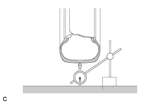
Using a dial indicator, check the runout of the tires.
Tire runout 1.0 mm (0.0394 in.) or less
-
-
MEASURE VEHICLE HEIGHT

-
Bounce the vehicle at the corners up and down to stabilize the suspension and inspect the vehicle height.
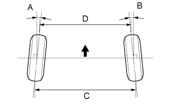
Standard vehicle height (unloaded) Front (A - B) Rear (C - D) 146 mm (5.75 in.) 83 mm (3.27 in.) Measuring points A Ground clearance of front wheel center B Ground clearance of head center of bolt used to install the front No. 1 suspension lower arm to the front suspension member C Ground clearance of rear wheel center D Ground clearance of pit center of the attachment rear suspension arm Note
-
The standard value shown here is a value that is used for adjusting the wheel alignment and does not indicate the height of an actual vehicle.
-
Before inspecting the wheel alignment, adjust the vehicle height to the specified value.
If the vehicle height is not as specified, adjust the height by pressing down on the vehicle several times to stabilize the suspension.
-
-
-
INSPECT CAMBER, CASTER AND STEERING AXIS INCLINATION
-
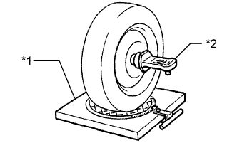
Text in Illustration *1 Alignment Tester *2 Camber - Caster - Steering axis inclination Gauge Put the front wheels on the center of the alignment tester.
-
Remove the center ornament.
-
Install the camber-caster-steering axis inclination gauge at the center of the axle hub or drive shaft.
-
Inspect the camber, caster and steering axis inclination.
Standard camber inclination (unloaded) Camber Inclination Camber
Left - right error
-0°40' +/-45' (-0.67° +/-0.75°)
30' (0.50°) or less
Standard caster inclination (unloaded) Caster Inclination Caster
Left - right error
4°58' +/-45' (4.97° +/-0.75°)
45' (0.75°) or less
Standard steering axis inclination (unloaded) Steering Axis Inclination Steering axis
Left - right error
8°54' +/-45' (8.90° +/- 0.75°)
30' (0.50°) or less
Note
-
Inspect while the vehicle is empty.
-
The maximum tolerance of right and left difference for the camber is 30' or less.
-
The maximum tolerance of right and left difference for the caster is 45' or less.
-
-
Remove the camber-caster-steering axis inclination gauge and attachment.
-
Install the center ornament.
If the caster and steering axis inclinations are not within the specified values, after the camber has been correctly adjusted, recheck the suspension parts for damaged and/or worn out parts.
-
-
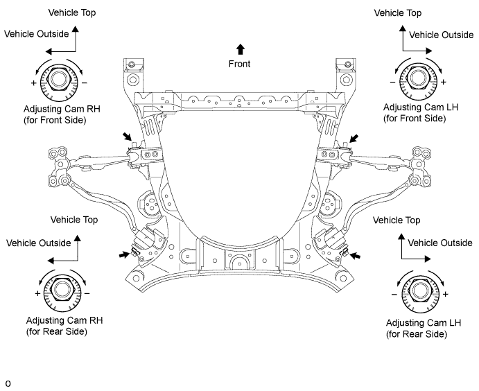
ADJUST CAMBER AND CASTER
-
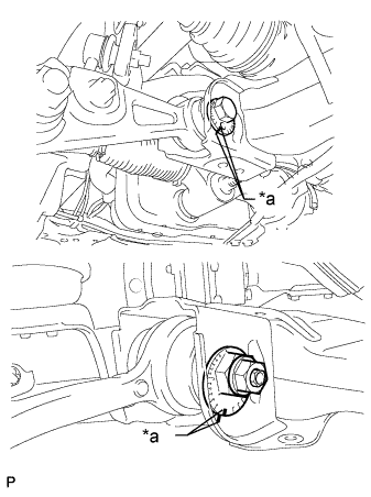
Text in Illustration *a Matchmark Put matchmarks on the adjusting cam (front side) and adjusting cam (rear side).
-
Loosen the nut of the adjusting cam (front side) and the bolt of the adjusting cam (rear side).
-
Turn the adjusting cam, and adjust the camber and caster.
-
Refer to the adjustment table to make adjusting easier.
-
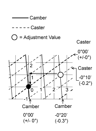
Refer to the following example on how to use the adjustment table.
Standard value (reference) Camber Caster -0°40' (-0.67°) 4°58' (4.97°) Measured value (reference) Camber Caster -1° 4°48' (4.8°)
-
Calculate the adjustment value by using the formula below.
Adjustment value (reference) - Camber Caster Adjustment Value -0°20' (-0.3°) -0°10' (-0.2°) Formula:
Adjustment Value = Measured Value - Standard Value
-
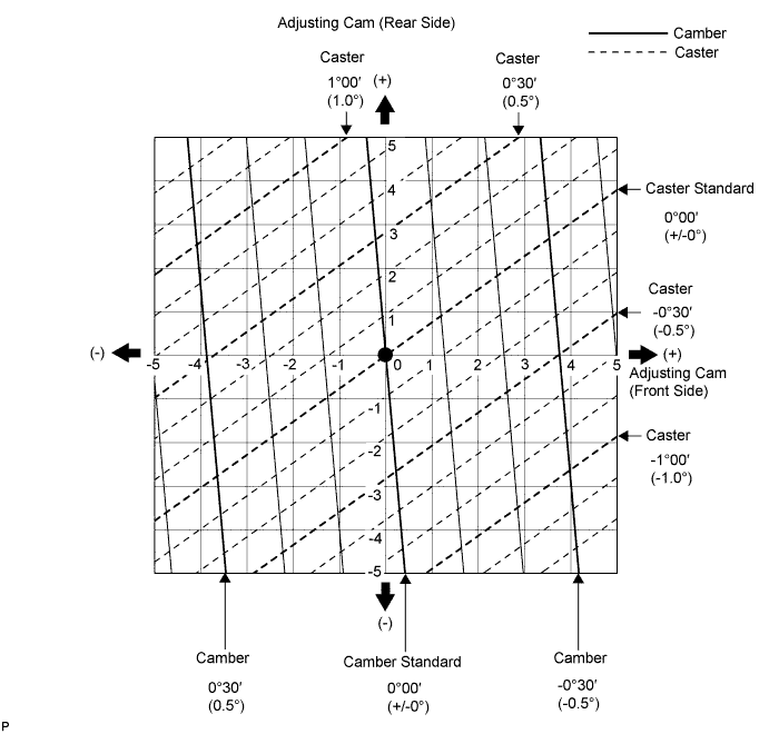
Mark the adjustment value point on the adjustment table. Then obtain the adjusting cam turning distance from the adjustment table so that the adjustment value point becomes zero.
Amount to turn adjusting cams (by gradation) - Adjusting Cam Turning Distance Adjusting Cam
(Front Side)
Approximately 2.5 notches in minus direction Adjusting Cam
(Rear Side)
Approximately 1.0 marking in minus direction
-
-
Adjustment Table
-
Tighten the nut of the adjusting cam (front side) and the bolt of the adjusting cam (rear side).
- Torque:
- 210 N*m { 2141 kgf*cm, 155 ft.*lbf }
-
Inspect the toe-in.
-
Inspect side slip.
-
-
ADJUST CAMBER
-
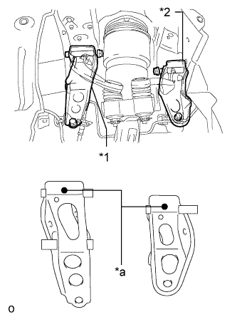
Text in Illustration *1 Inner No. 1 Arm Attachment Plate *2 Inner No. 2 Arm Attachment Plate *a Distinguishing Color If the right and left camber values are not within the specified value even though the camber and caster have been adjusted with the toe adjusting cam and camber adjusting cam, replace the inner No. 1 and No. 2 arm attachment plates and perform the camber adjustment.
Standard - Inner No. 1 Arm Attachment Plate Inner No. 2 Arm Attachment Plate Camber Angle Change Caster Angle Change - RH LH RH LH - - Arm Attachment Part No. and Distinguishing Color Standard Part 48614-50010
(Yellow)
48617-50010
(Yellow)
48614-50020
(White)
48617-50020
(White)
0 (Standard) 0 (Standard) + 2 mm Part 48614-50030
(Pink)
48617-50030
(Pink)
48614-50050
(Blue)
48617-50050
(Blue)
+ 12.0' + 1' Tech Tips
For +2 mm parts, the upper arm installation hole is further toward the outside of the vehicle compared to standard parts.
-
-
INSPECT TOE-IN
-
Bounce the vehicle up and down at the corners to stabilize the suspension and inspect toe-in.
Toe-in (unloaded) Item Standard toe-in Toe-in
(total)
A + B: 0°00' +/-10' (0.00°+/-0.16°)
C - D: 0 +/-2 mm (0 +/-0.0787 in.)
If toe-in is not within the specified range, adjust it at the rack ends.
-
-
ADJUST TOE-IN
-
Measure the thread lengths of the right and left rack ends.
Standard Difference in thread length of 1.5 mm (0.0591 in.) or less -
Remove the rack boot set clips.
-
Loosen the tie rod end lock nuts.
-
Adjust the rack ends if the difference in thread length between the right and left rack ends is not within the specified range.
-
Extend the shorter rack end if the measured toe-in deviates toward the outer-side.
-
Shorten the longer rack end if the measured toe-in deviates toward the inner-side.
-
-
Turn the right and left rack ends by an equal amount to adjust toe-in.
Tech Tips
Try to adjust toe-in to the center of the specified range.
-
Make sure that the lengths of the right and left rack ends are the same.
-
Text in Illustration *1 Lock Nut Tighten the tie rod end lock nuts.
- Torque:
- 56 N*m { 571 kgf*cm, 41 ft.*lbf }
Note
Partially tighten the lock nut while holding the hexagonal part of the steering rack end so that the lock nut and the steering rack end do not turn together. Hold the width across flat of the tie rod end and tighten the lock nut.
-
Perform the VGRS system calibration Click here.
-
Place the boots on the seats and install the clips.
Tech Tips
-
Make sure that the boots are not twisted.
-
Make sure that the clips are facing towards the front of the vehicle.
-
-
-
INSPECT WHEEL ANGLE
-
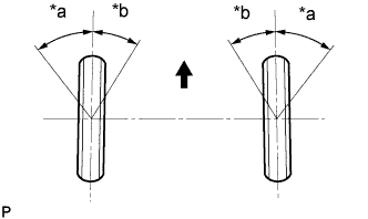
Text in Illustration *a Inside *b Outside 
Front of Vehicle Turn the steering wheel fully to the left and right and measure the turning angle.
Standard wheel turning angle Inside wheel Outside wheel: Reference 38°02' +/-2° (38.03°+/-2°) 33°39' (33.65°) If the right and left inside wheel angles differ from the specified range, check the right and left rack end lengths.
-
-
INSPECT FRONT SUSPENSION
-
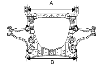
Inspect the front suspension member.
-
Measure the length between the installation bolts of the front No. 1 suspension lower arm and front No. 2 suspension lower arm.
Standard length 846.8 mm (33.3 in.) (A) 856 mm (33.7 in.) (B) If the result is not within the specification, replace the front suspension member.
-
-
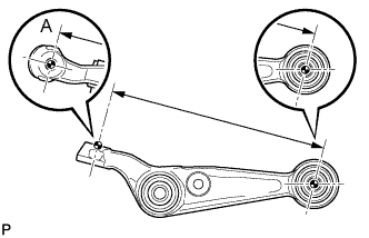
Inspect the front No. 1 suspension lower arm.
-
Remove the front No. 1 suspension lower arm Click here.
-
Measure the dimension between the center of the front No. 1 suspension lower arm bush and position A.
Standard length 286.1 mm (11.3 in.) Tech Tips
If the dimension of the front suspension lower arm changes 2 mm (0.0787 in.), the camber will change approximately 16' (0.3°).
-
-
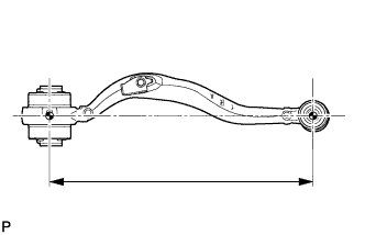
Inspect the front No. 2 suspension lower arm.
-
Remove the front No. 2 suspension lower arm Click here.
-
Measure the dimension between the center of the front suspension lower arm bush and the ball joint stud.
Standard length 399.5 mm (15.7 in.) Tech Tips
If the dimension of the front suspension lower arm changes 2 mm (0.0787 in.), the camber will change approximately 1' (0.02°).
-
-
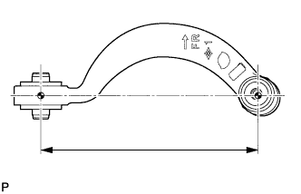
Inspect the front No. 1 suspension upper arm.
-
Remove the front No. 1 suspension upper arm Click here.
-
Measure the dimension between the center of the front No. 1 suspension upper arm bush and the ball joint stud.
Standard length 235.8 mm (9.28 in.) Tech Tips
If the dimension of the front suspension upper arm changes 2 mm (0.0787 in.), the camber will change approximately 7' (0.12°).
-
-
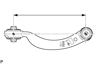
Inspect the front No. 2 suspension upper arm.
-
Remove the front No. 2 suspension upper arm Click here.
-
Measure the dimension between the center of the front No. 2 suspension upper arm bush and the ball joint stud.
Standard length 233 mm (9.17 in.) Tech Tips
If the dimension of the front suspension upper arm changes 2 mm (0.0787 in.), the camber will change approximately 6' (0.1°).
-
-
-
PLACE FRONT WHEELS FACING STRAIGHT AHEAD
-
REMOVE COWL TOP VENTILATOR LOUVER RH
-

for LHD:
Remove the 6 clips and cowl top ventilator louver RH.
-

for RHD:
Remove the 6 clips and cowl top ventilator louver LH.
-
-
PRECAUTION
Note
After turning the engine switch off, waiting time may be required before disconnecting the cable from the battery terminal. Therefore, make sure to read the disconnecting the cable from the battery terminal notice before proceeding with work Click here.
-
DISCONNECT CABLE FROM NEGATIVE BATTERY TERMINAL
Note
-
When disconnecting the cable, some systems need to be initialized after the cable is reconnected Click here.
-
Disconnect the cable from the negative battery terminal for 2 seconds or more.
-
-
CONNECT CABLE TO NEGATIVE BATTERY TERMINAL
-
INSTALL COWL TOP VENTILATOR LOUVER RH
-
for LHD:
Install the 6 clips and cowl top ventilator louver RH.
Note
If the cowl top ventilator louver RH is not properly installed, water may leak into the engine room and cause malfunctions. Therefore, make sure the cowl top ventilator louver RH is installed properly.
-
for RHD:
Install the 6 clips and cowl top ventilator louver LH.
Note
If the cowl top ventilator louver LH is not properly installed, water may leak into the engine room and cause malfunctions. Therefore, make sure the cowl top ventilator louver LH is installed properly.
-
-
PERFORM YAW RATE AND DECELERATION SENSOR ZERO POINT CALIBRATION
-
INITIALIZE ROTATION ANGLE SENSOR AND CALIBRATE TORQUE SENSOR ZERO POINT