AIR SUSPENSION SYSTEM TS and CG Terminal Circuit
DESCRIPTION
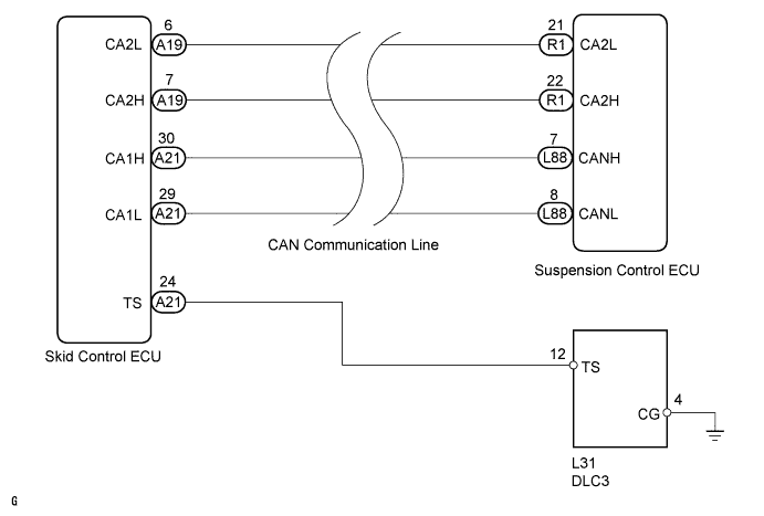
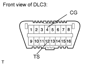
Connect terminals 12 (TS) and 4 (CG) of the DLC3 with the engine switch off. When the engine switch is turned to the on (IG) position, test mode will start and then the DTCs will be output.
WIRING DIAGRAM
INSPECTION PROCEDURE
Note
When replacing the skid control ECU, perform initialization of linear solenoid valve calibration Click here.
PROCEDURE
-
INSPECT DLC3 (TS VOLTAGE)
-
Measure the voltage according to the value in the table below.
Standard voltage Tester Connection Switch Condition Specified Condition L31-12 (TS) - L31-4 (CG) Engine switch on (IG) 10 to 14 V Result Result Proceed to NG A OK B
B 
PROCEED TO NEXT CIRCUIT INSPECTION SHOWN IN PROBLEM SYMPTOMS TABLE Click here
A 
-
-
CHECK HARNESS AND CONNECTOR (DLC3 - SKID CONTROL ECU AND BODY GROUND)
-
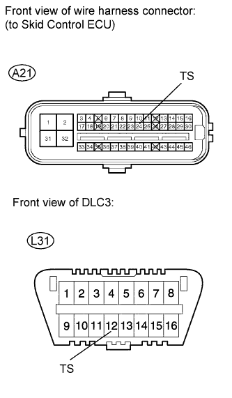
Disconnect the A21 skid control ECU connector.
-
Measure the resistance according to the value in the table below.
Standard resistance Tester Connection Switch Condition Specified Condition L31-12 (TS) - A21-24 (TS) Always Below 1 Ω L31-12 (TS) or A21-24 (TS) - Body ground Always 10 kΩ or higher L31-4 (CG) - Body ground Always Below 1 Ω Result Result Proceed to NG A OK (for LHD) B OK (for RHD) C
B
REPLACE SKID CONTROL ECU (for LHD) Click here
C
REPLACE SKID CONTROL ECU (for RHD) Click here
A 
REPAIR OR REPLACE HARNESS OR CONNECTOR
-