AIR SUSPENSION SYSTEM ECU Power Source Circuit
DESCRIPTION
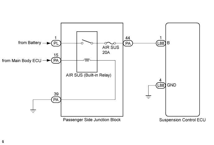
When the engine switch is on (IG), the driver side junction block AIR SUS relay turns ON, and power is supplied to the suspension control ECU.
WIRING DIAGRAM
INSPECTION PROCEDURE
Note
-
Before performing troubleshooting, inspect the connectors of related circuits.
-
Before replacing the suspension control ECU, perform all of the following again: 1) symptom simulation Click here; 2) DTC inspection; and 3) intelligent tester inspection (ECU Data List or Active Test). If no malfunctions are found in other areas, replace the suspension control ECU.
-
If the suspension control ECU or height control sensor is replaced, the vehicle height offset calibration must be performed Click here.
PROCEDURE
-
CHECK IG VOLTAGE (DATA LIST)
-
Turn the engine switch off.
-
Connect the intelligent tester to the DLC3.
-
Turn the engine switch on (IG) and turn the tester ON.
-
Enter the following menus:
Select: Chassis / Air suspension / Data List /
-
Check the values by referring to the table below.
Air suspension Tester Display Measurement Item/Range Normal Condition Diagnostic Note IG Power source Voltage ECU power supply voltage/
min.: 0.0 V
max.: 25.5 V
Engine switch on (IG): 11 to 14 V - OK 11 to 14 V Result Result Proceed to NG A OK B
B 
PROCEED TO NEXT CIRCUIT INSPECTION SHOWN IN PROBLEM SYMPTOMS TABLE Click here
A 
-
-
INSPECT FUSE (AIR SUS)
-
Remove the AIR SUS fuse from the passenger side junction block.
-
Measure the resistance according to the value(s) in the table bwlow.
Standard resistance Tester Connection Condition Specified Condition AIR SUS fuse Always Below 1 Ω
NG 
CHECK HARNESS AND CONNECTOR (PASSENGER SIDE JUNCTION BLOCK - ECU) Click here
OK
-
-
INSPECT PASSENGER SIDE JUNCTION BLOCK (AIR SUS RELAY)
-
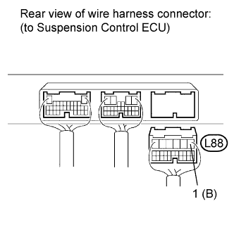
Disconnect the L88 ECU connector.
-
Measure the voltage according to the value(s) in the table below.
Standard voltage Tester Connection Switch Condition Specified Condition L88-1 (B) - L88-4 (GND) Engine switch on (IG) 11 to 14 V Result Result Proceed to NG A OK (for LHD) B OK (for RHD) C
B
REPLACE SUSPENSION CONTROL ECU (for LHD) Click here
C
REPLACE SUSPENSION CONTROL ECU (for RHD) Click here
A
-
-
CHECK HARNESS AND CONNECTOR (PASSENGER SIDE JUNCTION BLOCK - ECU AND BODY GROUND)
-
Disconnect the L88 ECU connector.
-
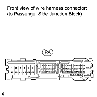
Disconnect the PA passenger side junction block connector.
-
Measure the resistance according to the value in the table below.
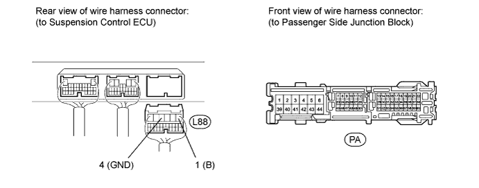
Standard resistance Tester Connection Condition Specified Condition L88-1 (B) - PA-44 Always Below 1 Ω L88-4 (GND) - Body ground Always Below 1 Ω
NG
REPAIR OR REPLACE HARNESS OR CONNECTOR
OK
-
-
CHECK HARNESS AND CONNECTOR (BATTERY - PASSENGER SIDE JUNCTION BLOCK)
-
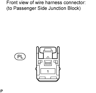
Disconnect the PL junction block connector.
-
Measure the voltage according to the value(s) in the table below.
Standard voltage Tester Connection Condition Specified Condition PL-1 - Body ground Always 11 to 14 V
NG
REPAIR OR REPLACE HARNESS OR CONNECTOR
OK
-
-
CHECK HARNESS AND CONNECTOR (MAIN BODY ECU - JUNCTION BLOCK AND BODY GROUND)
-
Disconnect the PA junction block connector.
-
Measure the voltage and resistance according to the value(s) in the table below.
Standard voltage Tester Connection Switch Condition Specified Condition PA-15 - Body ground Engine switch on (IG) 11 to 14 V Standard resistance Tester Connection Condition Specified Condition PA-39 - Body ground Always Below 1 Ω
NG
REPAIR OR REPLACE HARNESS OR CONNECTOR
OK
-
-
CHECK HARNESS AND CONNECTOR (PASSENGER SIDE JUNCTION BLOCK - ECU)
-
Disconnect the L88 ECU connector.
-
Connect the PA passenger side junction block connector.
-
Measure the resistance according to the value in the table below.
Standard resistance Tester Connection Condition Specified Condition L88-1 (B) - Body ground Always 10 kΩ or higher Tech Tips
If the fuse is blown, replace the fuse.
NG
REPAIR OR REPLACE HARNESS OR CONNECTOR
OK 
REPLACE PASSENGER SIDE JUNCTION BLOCK
-