REAR AXLE HUB INSTALLATION

Tech Tips
-
Use the same procedures for the RH side and LH side.
-
The procedures listed below are for the LH side.
-
A bolt without a torque specification is shown in the standard bolt chart ( Click here).
-
INSTALL REAR AXLE HUB AND BEARING ASSEMBLY LH
-
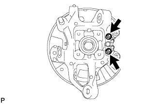
Install the parking brake plate, cable support bracket and parking brake anchor block to the rear axle carrier with the 2 nuts.
- Torque:
- 76 N*m { 775 kgf*cm, 56 ft.*lbf }
-
Hold the axle hub and bearing in a vise between aluminum plates.
Note
Do not overtighten the vise.
-
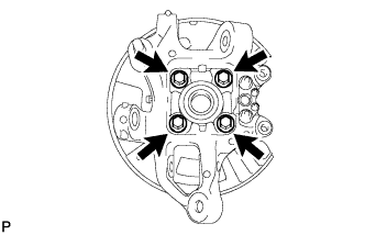
Install the axle hub and bearing to the rear axle carrier with the 4 bolts.
- Torque:
- 97 N*m { 989 kgf*cm, 72 ft.*lbf }
-
-
INSTALL REAR NO. 1 WHEEL BEARING DUST DEFLECTOR LH
-
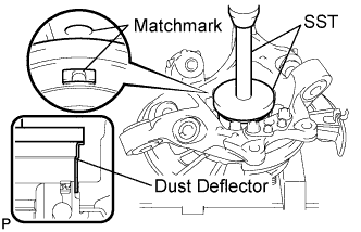
Using SST and a hammer, install the No. 1 bearing dust deflector to the rear axle carrier.
- SST
- 09950-70010 ( 09951-07150 )
- 09951-01000
Tech Tips
Align the hole for the speed sensor in the No. 1 bearing dust deflector with the rear axle carrier.
-
-
INSTALL REAR AXLE ASSEMBLY LH
-
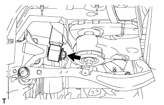
Engage the spline part of the rear axle carrier to the spline part of the driver shaft assembly.
-
Using a jack, lift up the rear axle carrier, and align the installation positions of each arm.
Note
Place a wooden block between the jack and rear axle carrier to prevent damage.
-
-
TEMPORARILY CONNECT REAR SHOCK ABSORBER ASSEMBLY LH (for Coil suspension)
-
Temporarily connect the rear shock absorber lower side with a new nut and washer to the axle carrier.
-
-
TEMPORARILY CONNECT PNEUMATIC CYLINDER WITH REAR SHOCK ABSORBER ASSEMBLY LH (for Air suspension)
-
Temporarily connect the pneumatic cylinder lower side with a new nut and washer to the axle carrier.
-
-
CONNECT REAR UPPER NO. 1 CONTROL ARM ASSEMBLY LH
-
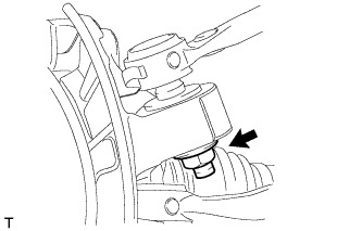
Connect the control arm with a new nut to the axle carrier.
- Torque:
- 160 N*m { 1632 kgf*cm, 118 ft.*lbf }
-
-
CONNECT REAR UPPER NO. 2 CONTROL ARM ASSEMBLY LH
-
Connect the control arm with a new nut to the axle carrier.
- Torque:
- 160 N*m { 1632 kgf*cm, 118 ft.*lbf }
-
-
TEMPORARILY TIGHTEN REAR NO. 2 SUSPENSION ARM ASSEMBLY LH
-
Install the stud of the suspension arm, and temporarily install a washer, nut and the bolt to the axle carrier.
-
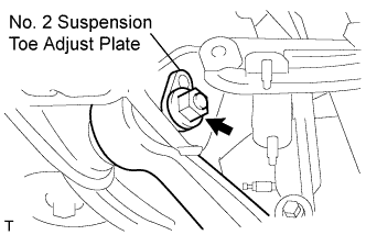
Temporarily install the No. 2 suspension arm with the No. 2 suspension toe adjust plate, rear suspension toe adjust cam and nut to the suspension member.
-
-
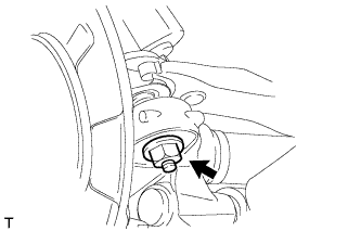
CONNECT TOE CONTROL LINK SUB-ASSEMBLY LH
-
Connect the control link with a new nut to the axle carrier.
- Torque:
- 118 N*m { 1203 kgf*cm, 87 ft.*lbf }
-
-
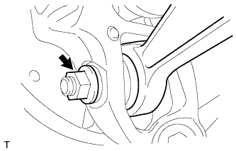
CONNECT REAR NO. 1 SUSPENSION ARM ASSEMBLY LH
-
Connect the suspension arm with a new nut to the axle carrier.
- Torque:
- 118 N*m { 1203 kgf*cm, 87 ft.*lbf }
-
-
INSTALL PARKING BRAKE ASSEMBLY
-
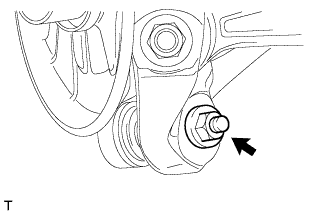
INSTALL REAR AXLE SHAFT LH NUT
-
Install a new rear axle shaft nut.
- Torque:
- 290 N*m { 2957 kgf*cm, 214 ft.*lbf }
-
-
INSPECT REAR AXLE HUB BEARING LOOSENESS
-
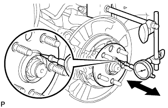
Using a dial indicator, check for looseness near the center of the axle hub.
Maximum 0.05 mm (0.0020 in.) Note
Ensure that the dial indicator is set at a right angle to the measurement surface.
If the looseness exceeds the maximum, replace the axle hub.
-
-
INSPECT REAR AXLE HUB RUNOUT
-
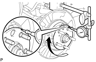
Using a dial indicator, check for runout on the surface of the axle hub outside the hub bolt.
Maximum 0.05 mm (0.0020 in.) Note
Ensure that the dial indicator is set at a right angle to the measurement surface.
If the runout exceeds the maximum, replace the axle hub.
-
-
INSTALL REAR DISC
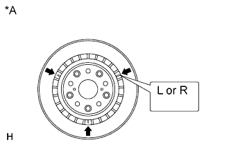
Text in Illustration *A for 17 inch Disc Note
The 17 inch disc has an identification mark. Make sure of the identification mark when installing the disc.
Item Identification mark 17 inch disc LH L 17 inch disc RH R Tech Tips
The 16 inch disc has no identification mark. The disc can be installed to the LH or RH side.
-
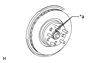
Text in Illustration *a Matchmark While aligning the matchmarks, install the rear disc.
Tech Tips
When replacing the rear disc with a new one, select the installation position where the rear disc has the minimum runout.
-
-
ADJUST PARKING BRAKE SHOE CLEARANCE
-
Adjust parking brake shoe clearance Click here.
-
-
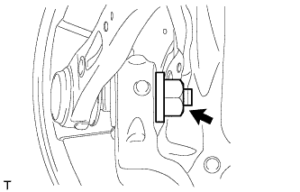
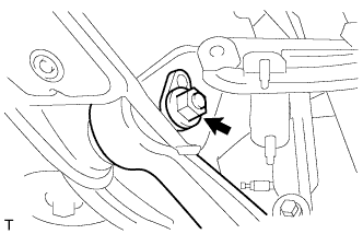
CONNECT SPEED SENSOR REAR LH
-
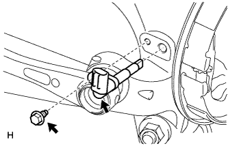
Install the sensor with the bolt.
- Torque:
- 8.5 N*m { 87 kgf*cm, 75 in.*lbf }
Note
-
The rear speed sensor is easily damaged. When installing the rear speed sensor to the rear axle hub RH, do not use excessive force to rotate and install it.
-
Prevent foreign matter from attaching to the sensor tip.
-
Do not drop the sensor. If the sensor has been dropped, replace the sensor with a new one.
-
-
CONNECT REAR DISC BRAKE CALIPER ASSEMBLY LH
-
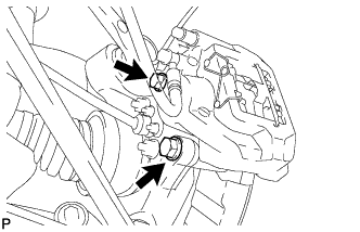
Connect the rear disc brake caliper assembly LH with new 2 bolts.
- Torque:
- 86 N*m { 877 kgf*cm, 63 ft.*lbf }
Note
-
Do not twist the flexible hose.
-
Make sure the screw parts are free from foreign matter and are not damaged.
-
Be careful not to overtighten the bolts, as the rear axle carrier is made of aluminum.
-
-
STAKE REAR AXLE SHAFT LH NUT
-
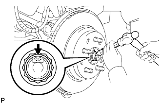
Using a chisel and a hammer, stake the axle shaft nut.
-
-
INSTALL LOAD SENSING VALVE SENSOR BRACKET
-
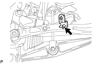
Install the load sensing valve sensor bracket to the toe control link sub-assembly with the bolt.
- Torque:
- 3.6 to 6.9 N*m { 37 to 70 kgf*cm, 32 to 61 in.*lbf }
-
-
STABILIZE SUSPENSION (for Coil Suspension)
-
Install the rear tires.
- Torque:
- 140 N*m { 1428 kgf*cm, 104 ft.*lbf }
-
Lower the vehicle and bounce it up and down several times to stabilize the rear suspension.
-
Remove the rear tires.
-
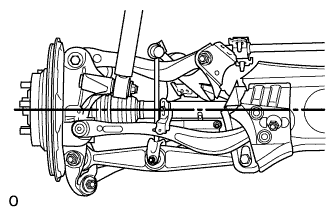
Jack up the axle carrier with a wooden block between the jack and axle carrier. Apply a load to the rear suspension so that the rear drive shaft assembly becomes level.
-
-
STABILIZE SUSPENSION (for Air Suspension)
-
Install the rear tires.
- Torque:
- 140 N*m { 1428 kgf*cm, 104 ft.*lbf }
-
Lower the vehicle and start the engine. Then fill the pneumatic cylinder assembly with rear shock absorber with air.
-
Lower the vehicle and bounce it up and down several times to stabilize the rear suspension.
-
Remove the rear tires.
-
Jack up the axle carrier with a wooden block between the jack and axle carrier. Apply a load to the suspension so that the rear drive shaft assembly is placed in a horizontal position.
-
-
CONNECT REAR SHOCK ABSORBER ASSEMBLY LH (for Coil suspension)
-
Connect the nut on the axle carrier.
- Torque:
- 80 N*m { 816 kgf*cm, 59 ft.*lbf }
-
-
CONNECT PNEUMATIC CYLINDER WITH REAR SHOCK ABSORBER ASSEMBLY LH (for Air suspension)
-
Connect the nut on the axle carrier.
- Torque:
- 80 N*m { 816 kgf*cm, 59 ft.*lbf }
-
-
CONNECT REAR STABILIZER LINK ASSEMBLY LH
-
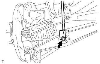
Insert the bolt from the front of the vehicle. Then install the rear stabilizer link assembly LH with the nut.
- Torque:
- 26 N*m { 265 kgf*cm, 19 ft.*lbf }
-
-
TIGHTEN REAR NO. 2 SUSPENSION ARM ASSEMBLY LH
-
Tighten the nut on the rear suspension member side.
- Torque:
- 150 N*m { 1530 kgf*cm, 111 ft.*lbf }
-
Tighten the nut on the rear axle carrier side.
- Torque:
- 225 N*m { 2294 kgf*cm, 166 ft.*lbf }
-
-
INSTALL REAR WHEEL
- Torque:
- 140 N*m { 1428 kgf*cm, 103 ft.*lbf }
-
PERFORM PARKING BRAKE SHOE BEDDING
-
Perform parking brake shoe bedding ( Click here).
-
-
INSPECT AND ADJUST REAR WHEEL ALIGNMENT
-
Inspect and adjust rear wheel alignment ( Click here).
-
-
CHECK ABS SPEED SENSOR SIGNAL
-
Check the speed sensor signal ( Click here).
-
-
ADJUST HEADLIGHT ASSEMBLY
-
ADJUST OBJECT RECOGNITION CAMERA