REAR AXLE HUB BOLT REPLACEMENT

-
REMOVE REAR WHEEL
-
REMOVE REAR DISC BRAKE CALIPER ASSEMBLY LH
-
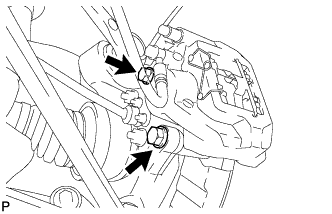
Remove the 2 bolts and disconnect the rear disc brake caliper assembly.
Note
-
Hang the caliper with wire or equivalent.
-
Do not damage the brake hose.
-
-
-
REMOVE REAR DISC
-
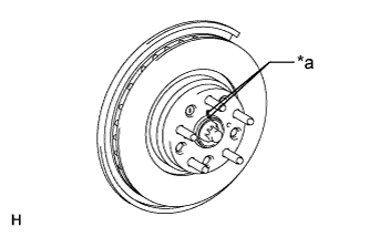
Text in Illustration *a Matchmark Put matchmarks on the rear disc and axle hub if planning to reuse the disc.
-
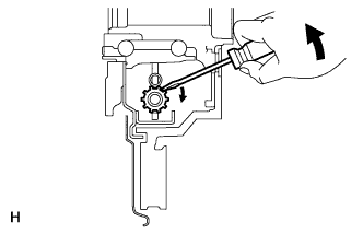
Turn the shoe adjuster until the disc turns freely, and then remove the disc.
-
-
REMOVE REAR AXLE LH HUB BOLT
-
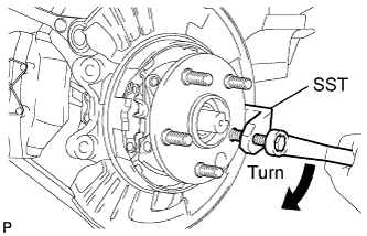
Using SST, remove the rear axle hub bolt.
- SST
- 09650-17011
-
-
INSTALL REAR AXLE LH HUB BOLT
-
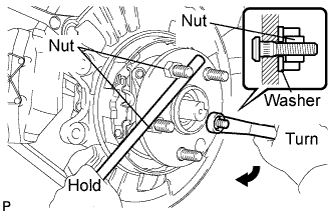
Install a washer and nut to a new bolt as shown in the illustration.
-
Using a screwdriver or an equivalent to hold the hub and bearing, install the rear axle hub bolt by tightening the nut.
Note
Do not damage the threads of the hub bolts.
-
-
INSTALL REAR DISC
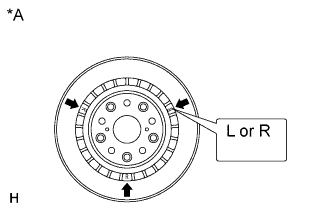
Text in Illustration *A for 17 inch Disc Note
The 17 inch disc has an identification mark. Make sure of the identification mark when installing the disc.
Item Identification mark 17 inch disc LH L 17 inch disc RH R Tech Tips
The 16 inch disc has no identification mark. The disc can be installed to the LH or RH side.
-
Text in Illustration *a Matchmark While aligning the matchmarks, install the rear disc.
Tech Tips
When replacing the rear disc with a new one, select the installation position where the rear disc has the minimum runout.
-
-
ADJUST PARKING BRAKE SHOE CLEARANCE
-
Temporarily install the hub nuts.
-
With the engine switch on (IG), operate the electric parking brake switch to release the parking brake. Then turn the engine switch off.
-
Remove the shoe adjusting hole plug, and rotate the rear disc so that the service hole is aligned with the adjusting screw.
-
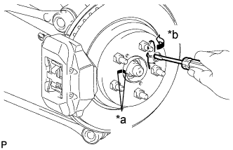
Text in Illustration *a Matchmark *b Contract Using a screwdriver, turn the adjusting screw of the parking brake shoe in the expansion direction until the disc locks.
-
With the engine switch on (IG), operate the electric parking brake switch to lock and release the parking brake. Repeat again. Then turn the engine switch off.
Note
Make sure that the parking brake is released.
-
Turn the adjusting screw again in the expansion direction to lock the disc.
-
Loosen the adjusting screw so that the rear disc can rotate slightly.
Tech Tips
The standard number of return notches is 7.
-
Check that there is no brake drag.
-
Install the shoe adjusting hole plug and remove the hub nuts.
-
-
INSTALL REAR DISC BRAKE CALIPER ASSEMBLY LH
-
Connect the rear disc brake caliper assembly LH with new 2 bolts.
- Torque:
- 86 N*m { 877 kgf*cm, 63 ft.*lbf }
Note
-
Do not twist the flexible hose.
-
Make sure the screw parts are free from foreign matter and are not damaged.
-
Be careful not to overtighten the bolts, as the rear axle carrier is made of aluminum.
-
-
INSTALL REAR WHEEL
- Torque:
- 140 N*m { 1428 kgf*cm, 103 ft.*lbf }