STEERING KNUCKLE (for 2WD) INSTALLATION

Tech Tips
-
Use the same procedures for the RH side and LH side.
-
The procedures listed below are for the LH side.
-
A bolt without a torque specification is shown in the standard bolt chart ( Click here).
-
INSTALL FRONT AXLE HUB SUB-ASSEMBLY LH
-

Install the front axle hub to the steering knuckle with the 4 bolts.
- Torque:
- 65 N*m { 663 kgf*cm, 48 ft.*lbf }
-
-
INSTALL STEERING KNUCKLE SUB-ASSEMBLY LH
-
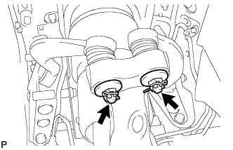
Install the steering knuckle to the front No. 1 suspension upper arm LH and front No. 2 suspension upper arm LH with the nuts.
- Torque:
- 60 N*m { 612 kgf*cm, 44 ft.*lbf }
-
Install new clips.
Note
If it is necessary to align the holes for the clips after installing the nuts, the nuts can be tightened up to 60° more.
-
-
CONNECT FRONT NO. 2 SUSPENSION LOWER ARM ASSEMBLY LH
-
Connect the front No. 2 suspension lower arm assembly LH to the steering knuckle with the nut.
- Torque:
- 145 N*m { 1479 kgf*cm, 107 ft.*lbf }
-
Install a new clip.
Note
If it is necessary to align the holes for the clip after installing the nut, the nut can be tightened up to 60° more.
-
-
CONNECT FRONT SHOCK ABSORBER ASSEMBLY LH
-
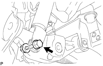
Install the bottom side of the front shock absorber assembly LH to the No. 2 suspension lower arm LH. Then insert the bolt from the rear of the vehicle and temporarily install it with the nut.
- Torque:
- 108 N*m { 1101 kgf*cm, 80 ft.*lbf }
-
-
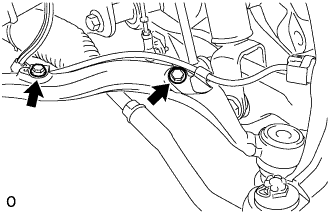
INSTALL FRONT STABILIZER LINK ASSEMBLY LH
-
Install the front stabilizer link with the 2 nuts.
- Torque:
- 84 N*m { 857 kgf*cm, 62 ft.*lbf }
Tech Tips
If the ball joint turns together with the nut, use a hexagon (6 mm) wrench to hold the stud.
-
-
CONNECT FRONT HEIGHT CONTROL SENSOR SUB-ASSEMBLY LH
-
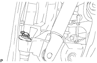
Install the bracket of the front height control sensor LH to the front No. 2 suspension lower arm LH with the bolt.
- Torque:
- 5.4 N*m { 55 kgf*cm, 48 in.*lbf }
-
-
CONNECT FRONT NO. 1 SUSPENSION LOWER ARM ASSEMBLY LH
-
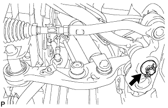
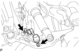
Connect the No. 1 suspension lower arm to the steering knuckle with the nut.
- Torque:
- 145 N*m { 1479 kgf*cm, 107 ft.*lbf }
-
Install a new clip.
Note
If it is necessary to align the holes for the clip after installing the nut, the nut can be tightened up to 60° more.
-
-
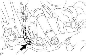
CONNECT TIE ROD ASSEMBLY LH
-
Connect the tie rod LH to the steering knuckle with the nut.
- Torque:
- 60 N*m { 612 kgf*cm, 44 ft.*lbf }
-
Install a new clip.
-
-
INSTALL FRONT DISC BRAKE DUST COVER LH
-
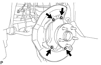
Install the front disc brake dust cover LH with the 4 bolts.
- Torque:
- 8.0 N*m { 82 kgf*cm, 71 in.*lbf }
-
-
INSTALL FRONT DISC
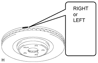
Note
Be sure to check the identification mark when installing the disc.
Item Identification mark LH LEFT RH RIGHT
-
Align the matchmarks and install the front disc.
Note
When replacing the front disc with a new one, select the installation position where the front disc has minimal runout.
-
-
CONNECT FRONT DISC BRAKE CALIPER ASSEMBLY LH
-
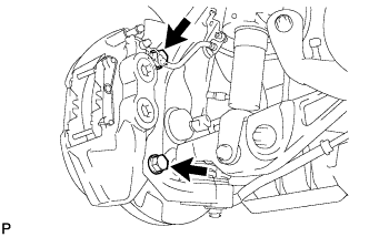
Install the front disc brake caliper assembly LH to the steering knuckle with the new 2 bolts.
- Torque:
- 135 N*m { 1377 kgf*cm, 100 ft.*lbf }
Note
-
Do not twist the flexible hose.
-
Make sure the screw parts are free from foreign matter and are not damaged.
-
Be careful not to overtighten the bolts, as the steering knuckle is made of aluminum.
-
Connect the flexible hose to the steering knuckle with the bolt.
- Torque:
- 20 N*m { 204 kgf*cm, 15 ft.*lbf }
-
-
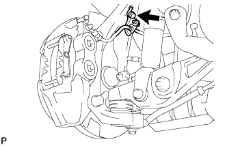
CONNECT SPEED SENSOR CONNECTOR LH
-
Connect the speed sensor connector to the speed sensor.
Note
-
Do not damage the tip of the speed sensor.
-
Do not allow foreign matter to contact the tip or installation area of the speed sensor.
-
Do not twist the speed sensor wire.
-
-
Install the speed sensor wire to the front No. 1 suspension lower arm with the 2 bolts.
- Torque:
- 8.5 N*m { 87 kgf*cm, 75 in.*lbf }
-
-
INSTALL FRONT WHEEL
-
INSPECT AND ADJUST FRONT WHEEL ALIGNMENT
-
Inspect and adjust front wheel alignment ( Click here).
-
-
CHECK ABS SPEED SENSOR SIGNAL
-
Check the speed sensor signal ( Click here).
-
-
ADJUST HEADLIGHT ASSEMBLY
-
ADJUST OBJECT RECOGNITION CAMERA