STEERING KNUCKLE (for 2WD) REMOVAL

Tech Tips
-
Use the same procedures for the RH side and LH side.
-
The procedures listed below are for the LH side.
-
REMOVE FRONT WHEEL
-
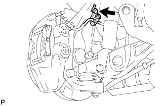
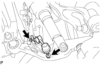
DISCONNECT SPEED SENSOR CONNECTOR LH
-
Remove the 2 bolts and disconnect the connector from the speed sensor.
Note
Do not twist the speed sensor wire.
-
-
DISCONNECT FRONT DISC BRAKE CALIPER ASSEMBLY LH
-
Remove the bolt and disconnect the flexible hose from the steering knuckle.
-
Remove the 2 bolts and front disc brake caliper assembly LH.
Note
-
Hang the front disc brake caliper assembly with a rope or wire.
-
Do not damage the brake hose.
-
-
-
REMOVE FRONT DISC
-
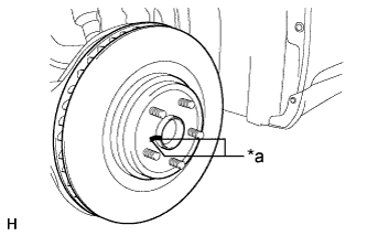
Text in Illustration *a Matchmark Remove the front disc from the front axle hub.
Tech Tips
Put matchmarks on the disc and axle hub.
-
-
REMOVE FRONT DISC BRAKE DUST COVER LH
-
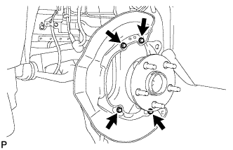
Remove the 4 bolts and front disc brake dust cover LH.
-
-
DISCONNECT TIE ROD ASSEMBLY LH
-
Remove the clip and nut.
-
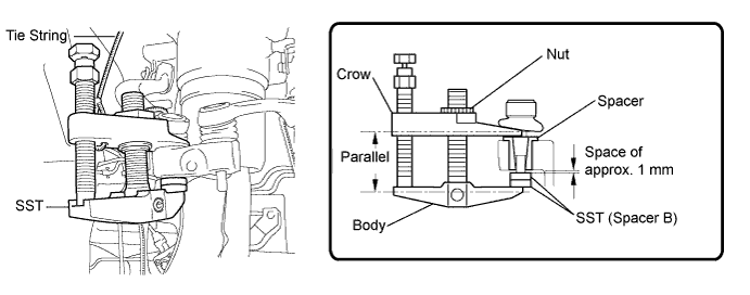
Install 2 spacers (SST spacer B) onto the tie rod assembly LH so that there is a space of approximately 1 mm (0.0397 in.) between the arm and spacers.
- SST
- 09960-20010 ( 09961-02060 )
Note
-
Make sure to install the spacers (SST spacer B) as the steering knuckle spacer may shift.
-
As SST may become damaged, make sure the space between the arm and spacers is not 1 mm (0.0397 in.) or less.
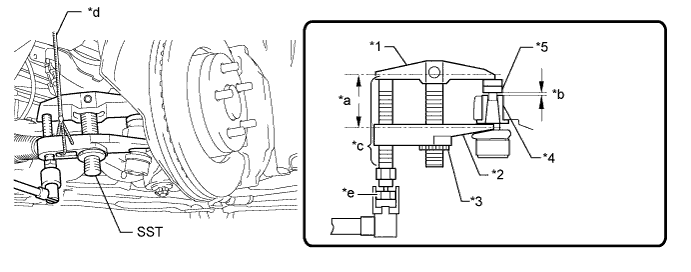
Text in Illustration *1 Body *2 Claw *3 Nut *4 Spacer B *a Parallel *b 1 mm (0.0397 in.) *c Molybdenum Grease Application Area *d String *e Place the wrench here - - Note
-
Do not damage the dust cover.
-
As the dust cover may be damaged, adjust SST with the center nut so that the body and crow are the parallel.
-
Make sure to tie the string of SST to the vehicle to prevent SST from dropping.
-
Using SST, disconnect the tie rod assembly from the steering knuckle.
- SST
- 09960-20010 ( 09961-02010 )
-
-
DISCONNECT FRONT NO. 1 SUSPENSION LOWER ARM ASSEMBLY LH
-
Remove the clip and nut.
-
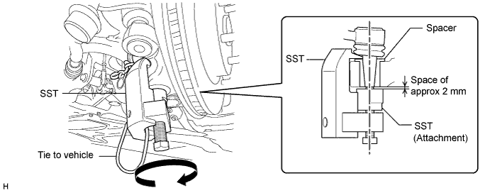
Install SST (attachment) to the front No. 1 suspension lower arm assembly LH so that there is a space of approximately 2 mm (0.0787 in.) between the arm and attachment.
- SST
- 09628-50010 ( 09628-05010 )
Note
-
Be sure to install SST (attachment) as the spacer may shift.
-
As SST may become damaged, make sure the space between the arm and attachment is not less than 2 mm (0.0787 in.).
-
Using SST, disconnect the front No. 1 suspension lower arm assembly LH from the steering knuckle.
- SST
- 09628-50010 ( 09628-05010 )
Note
-
Apply molybdenum grease to the bolt threads and end of the SST bolt.
-
Do not damage the dust cover of the lower arm No. 1.
-
Make sure that the bolt of SST and the ball joint are in a straight line when installing SST.
-
Be sure to tie the string of SST to the vehicle, to prevent SST from dropping.
-
Do not apply a torque of 160 N*m (1631 kgf*cm, 118 ft.*lbf) or more to SST as it may be damaged.
-
-
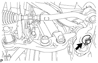
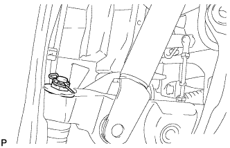
DISCONNECT FRONT HEIGHT CONTROL SENSOR SUB-ASSEMBLY LH
-
Remove the bolt, and then remove the bracket of the front height control sensor LH.
-
-
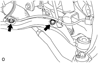
REMOVE FRONT STABILIZER LINK ASSEMBLY LH
-
Remove the 2 nuts and front stabilizer link assembly LH.
Tech Tips
If the stud bolt turns with the nut, use a 6 mm hexagon wrench to hold the stud.
-
-
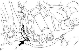
DISCONNECT FRONT SHOCK ABSORBER ASSEMBLY LH
-
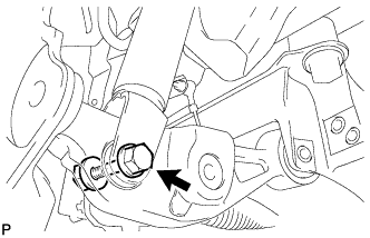
Remove the bolt and nut, and then disconnect the bottom side of the front shock absorber assembly LH from the front No. 2 suspension lower arm LH.
-
-
DISCONNECT FRONT NO. 2 SUSPENSION LOWER ARM ASSEMBLY LH
-
Remove the clip and nut.
-
Install SST (attachment) to the front No. 2 suspension lower arm assembly LH so that there is a space of approximately 2 mm (0.0787 in.) between the arm and attachment.

- SST
- 09628-50010 ( 09628-05010 )
Note
-
Be sure to install the SST (attachment) as the spacer may shift.
-
As SST may become damaged, make sure the space between the arm and attachment is not less than 2 mm (0.0787 in.).
-
Using SST, disconnect the front No. 2 suspension lower arm assembly LH from the steering knuckle.
- SST
- 09628-50010 ( 09628-05010 )
Note
-
Apply molybdenum grease to the bolt threads and end of the SST bolt.
-
Do not damage the dust cover of the No. 2 lower arm.
-
Make sure that the bolt of SST and the ball joint are in a straight line when installing SST.
-
Be sure to tie the string of SST to the vehicle to prevent SST from dropping.
-
Do not apply a torque of 160 N*m (1631 kgf*cm, 118 ft.*lbf) or more to SST as it may be damaged.
-
-
REMOVE STEERING KNUCKLE SUB-ASSEMBLY LH
-
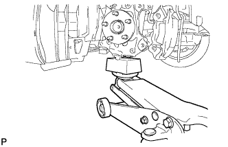
Support the steering knuckle LH with a jack and wooden block.
-
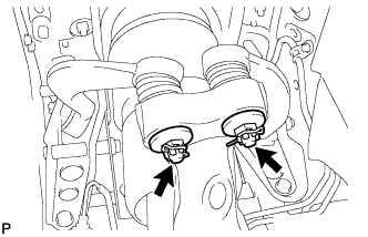
Remove the 2 clips and 2 nuts.
-
Install 2 spacers (SST spacer B) onto the front No. 1 suspension upper arm assembly LH so that there is a space of approximately 1 mm (0.0394 in.) between the arm and spacers.
- SST
- 09960-20010 ( 09961-02060 )
Note
-
Make sure to install the spacers (SST spacer B) as the steering knuckle spacer may shift.
-
As SST may become damaged, make sure the space between the arm and spacers is not 1 mm (0.0394 in.) or less.
-
Using SST, disconnect the front No. 1 suspension upper arm from the steering knuckle.
- SST
- 09960-20010 ( 09961-02010 )
Note
-
Apply molybdenum grease to the bolt threads and end of the SST bolt.
-
Do not damage the dust cover.
-
As the dust cover may be damaged, adjust SST with the center nut so that the body and crow are parallel.
-
Make sure to tie the string of SST to the vehicle to prevent SST from dropping.
-
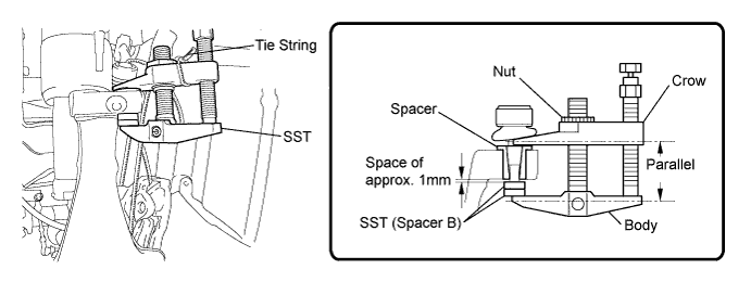
Install 2 spacers (SST spacer B) onto the front No. 2 suspension upper arm assembly LH so that there is a space of approximately 1 mm (0.0394 in.) between the arm and spacers.
- SST
- 09960-20010 ( 09961-02060 )
Note
-
Make sure to install the spacers (SST spacer B) as the steering knuckle spacer may shift.
-
As SST may become damaged, make sure the space between the arm and spacers is not 1 mm (0.0394 in.) or less.
-
Using SST, disconnect the front No. 2 suspension upper arm from the steering knuckle.
- SST
- 09960-20010 ( 09961-02010 )
Note
-
Apply molybdenum grease to the bolt threads and end of the SST bolt.
-
Do not damage the dust cover.
-
As the dust cover may be damaged, adjust SST with the center nut so that the body and crow are parallel.
-
Make sure to tie the string of SST to the vehicle to prevent SST from dropping.
-
-
REMOVE FRONT AXLE HUB SUB-ASSEMBLY LH
-

Remove the 4 bolts and front axle hub from the steering knuckle.
-