AIR SUSPENSION SYSTEM, Diagnostic DTC:C1711, C1712, C1713, C1714

| DTC Code | DTC Name |
|---|---|
| C1711 | Front Height Control Sensor RH Circuit Malfunction |
| C1712 | Front Height Control Sensor LH Circuit Malfunction |
| C1713 | Rear Height Control Sensor RH Circuit Malfunction |
| C1714 | Rear Height Control Sensor LH Circuit Malfunction |
DESCRIPTION
The height control sensor changes its resistance value based on changes in vehicle height. The suspension control ECU outputs a fixed voltage of 5 V to the height control sensor's SHB terminal. If the sensor's resistance value changes, the sensor's voltage value changes accordingly. The suspension control ECU then inputs the voltage value from the sensor to detect the vehicle height change.
| DTC No. | Detection Condition | Trouble Area |
|---|---|---|
| C1711/11 | With the engine switch on (IG), a voltage of 4.7 V or more, or 0.3 V or less at right front height control sensor is detected for 1 second. |
|
| C1712/12 | With the engine switch on (IG), a voltage of 4.7 V or more, or 0.3 V or less at left front height control sensor is detected for 1 second. |
|
| C1713/13 | With the engine switch on (IG), a voltage of 4.7 V or more, or 0.3 V or less at right rear height control sensor is detected for 1 second. |
|
| C1714/14 | With the engine switch on (IG), a voltage of 4.7 V or more, or 0.3 V or less at left rear height control sensor is detected for 1 second. |
|
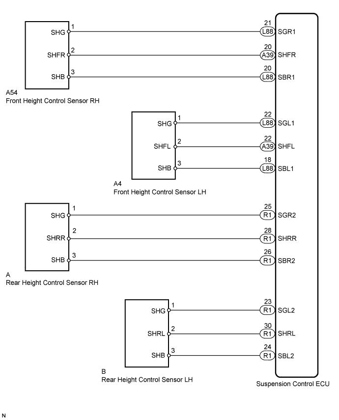
WIRING DIAGRAM
INSPECTION PROCEDURE
Note
-
Before performing troubleshooting, inspect the connectors of related circuits.
-
If DTC C1782/82 (Power Source Voltage Malfunction) is output at the same time, perform troubleshooting for C1782/82 first Click here.
-
Before replacing the suspension control ECU, perform all of the following again: 1) symptom simulation Click here; 2) DTC inspection; and 3) intelligent tester inspection (ECU Data List or Active Test). If no malfunctions are found in other areas, replace the suspension control ECU.
-
If the suspension control ECU or height control sensor is replaced, the vehicle height offset calibration must be performed Click here.
PROCEDURE
-
INSPECT HEIGHT CONTROL SENSOR
-
Check the front height control sensor:
-
Remove the front height control sensor RH or front height control sensor LH Click here.
Note
Do not drop the height control sensor. If it is dropped, replace it with a new one.
-
Connect 3 1.5 V dry cell batteries in series.
-
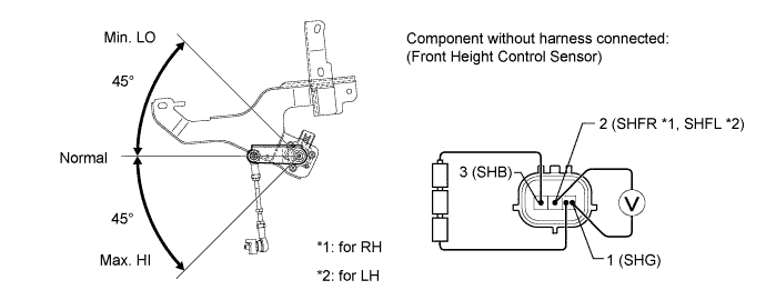
Connect the positive (+) end of the battery to terminal 3 (SHB) of the height control sensor and the negative (-) end of the battery to terminal 1 (SHG). While applying 4.5 V, slowly moving the sensor's link up and down, and measure the voltage between terminal 2 (SHFR*1 or SHFL*2) and terminal 1 (SHG).
Tech Tips
*1: for RH
*2: for LH
Standard voltage for RH Tester Connection Condition Specified Condition 2 (SHFR) - 1 (SHG) Max. HI Approx. 4.1 V Normal Approx. 2.25 V Min. LO Approx. 0.45 V for LH Tester Connection Condition Specified Condition 2 (SHFL) - 1 (SHG) Max. HI Approx. 4.1 V Normal Approx. 2.25 V Min. LO Approx. 0.45 V Note
Do not apply a voltage of higher than 6 V.
-
-
Check the rear height control sensor:
-
Remove the rear height control sensor RH or rear height control sensor LH Click here.
Note
Do not drop the height control sensor. If it is dropped, replace it with a new one.
-
Connect 3 1.5 V dry cell batteries in series.
-
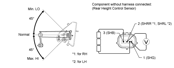
Connect the positive (+) end of the battery to terminal 3 (SHB) of the height control sensor and the negative (-) end of the battery to terminal 1 (SHG). While applying 4.5 V, slowly moving the sensor's link up and down, and measure the voltage between terminal 2 (SHRR*1 or SHRL*2) and terminal 1 (SHG).
Tech Tips
*1: for RH
*2: for LH
Standard voltage for RH Tester Connection Condition Specified Condition 2 (SHRR) - 1 (SHG) Max. HI Approx. 4.1 V Normal Approx. 2.25 V Min. LO Approx. 0.45 V for LH Tester Connection Condition Specified Condition 2 (SHRL) - 1 (SHG) Max. HI Approx. 4.1 V Normal Approx. 2.25 V Min. LO Approx. 0.45 V Note
Do not apply a voltage of higher than 6 V.
Result Condition Proceed to OK A Front height control sensor RH malfunction B Front height control sensor LH malfunction C Rear height control sensor RH malfunction D Rear height control sensor LH malfunction E -
B 
REPLACE FRONT HEIGHT CONTROL SENSOR RH Click here
C
REPLACE FRONT HEIGHT CONTROL SENSOR LH Click here
D
REPLACE REAR HEIGHT CONTROL SENSOR RH Click here
E
REPLACE REAR HEIGHT CONTROL SENSOR LH Click here
A 
-
-
CHECK HARNESS AND CONNECTOR (HEIGHT CONTROL SENSOR - SUSPENSION CONTROL ECU)
-
Check the front height control sensor RH harness and connector (when DTC C1711 is output).
-
Turn the engine switch off.
-
Disconnect the A39 and L88 ECU connectors.
-
Disconnect the A54 sensor connector.
-
Measure the resistance according to the value(s) in the table below.
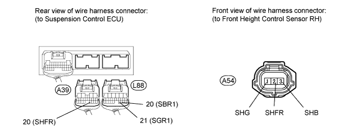
Standard resistance Tester Connection Condition Specified Condition A54-1 (SHG) - L88-21 (SGR1) Always Below 1 Ω A54-2 (SHFR) - A39-20 (SHFR) Always Below 1 Ω A54-3 (SHB) - L88-20 (SBR1) Always Below 1 Ω A54-1 (SHG) or L88-21 (SGR1) - Body ground Always 10 kΩ or higher A54-2 (SHFR) or A39-20 (SHFR) - Body ground Always 10 kΩ or higher A54-3 (SHB) or L88-20 (SBR1) - Body ground Always 10 kΩ or higher
-
-
Check the front height control sensor LH harness and connector (when DTC C1712 is output).
-
Turn the engine switch off.
-
Disconnect the A39 and L88 ECU connectors.
-
Disconnect the A4 sensor connector.
-
Measure the resistance according to the value(s) in the table below.
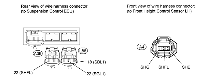
Standard resistance Tester Connection Condition Specified Condition A4-1 (SHG) - L88-22 (SGL1) Always Below 1 Ω A4-2 (SHFL) - A39-22 (SHFL) Always Below 1 Ω A4-3 (SHB) - L88-18 (SBL1) Always Below 1 Ω A4-1 (SHG) or L88-22 (SGL1) - Body ground Always 10 kΩ or higher A4-2 (SHFL) or A39-22 (SHFL) - Body ground Always 10 kΩ or higher A54-3 (SHB) or L88-18 (SBL1) - Body ground Always 10 kΩ or higher
-
-
Check the rear height control sensor RH harness and connector (when DTC C1713 is output).
-
Turn the engine switch off.
-
Disconnect the R1 ECU connector.
-
Disconnect the "A" sensor connector.
-
Measure the resistance according to the value(s) in the table below.
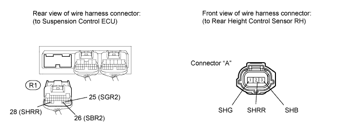
Standard resistance Tester Connection Condition Specified Condition "A"-1 (SHG) - R1-25 (SGR2) Always Below 1 Ω "A"-2 (SHRR) - R1-28 (SHRR) Always Below 1 Ω "A"-3 (SHB) - R1-26 (SBR2) Always Below 1 Ω "A"-1 (SHG) or R1-25 (SGR2) - Body ground Always 10 kΩ or higher "A"-2 (SHRR) or R1-28 (SHRR) - Body ground Always 10 kΩ or higher "A"-3 (SHB) or R1-26 (SBR2) - Body ground Always 10 kΩ or higher
-
-
Check the rear height control sensor LH harness and connector (when DTC C1714 is output).
-
Turn the engine switch off.
-
Disconnect the R1 ECU connector.
-
Disconnect the "B" sensor connector.
-
Measure the resistance according to the value(s) in the table below.
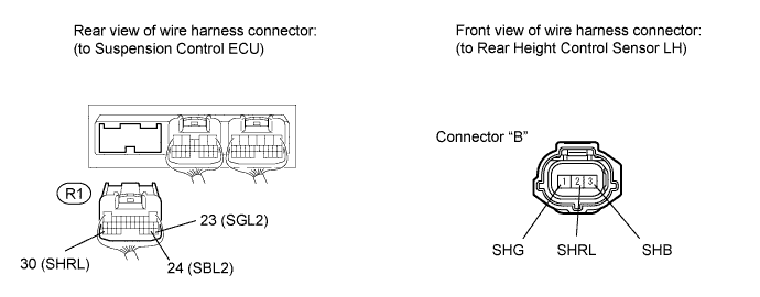
Standard resistance Tester Connection Condition Specified Condition "B"-1 (SHG) - R1-23 (SGL2) Always Below 1 Ω "B"-2 (SHRL) - R1-30 (SHRL) Always Below 1 Ω "B"-3 (SHB) - R1-24 (SBL2) Always Below 1 Ω "B"-1 (SHG) or R1-23 (SGL2) - Body ground Always 10 kΩ or higher "B"-2 (SHRL) or R1-30 (SHRL) - Body ground Always 10 kΩ or higher "B"-3 (SHB) or R1-24 (SBL2) - Body ground Always 10 kΩ or higher Result Result Proceed to NG A OK (for LHD) B OK (for RHD) C
-
B
REPLACE SUSPENSION CONTROL ECU (for LHD) Click here
C
REPLACE SUSPENSION CONTROL ECU (for RHD) Click here
A 
REPAIR OR REPLACE HARNESS OR CONNECTOR
-