DIFFERENTIAL MOUNT CUSHION REMOVAL

-
REMOVE PROPELLER WITH CENTER BEARING SHAFT ASSEMBLY
-
REMOVE NO. 2 DIFFERENTIAL SUPPORT PROTECTOR
-
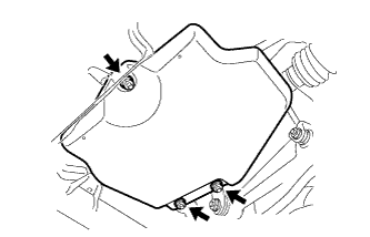
Remove the 3 nuts and differential support protector.
-
-
REMOVE NO. 1 DIFFERENTIAL SUPPORT PROTECTOR
Tech Tips
Use the same procedure described for the No. 2 differential support protector.
-
REMOVE REAR SUSPENSION MEMBER BRACE LH
-
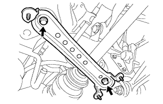
Remove the 2 bolts and rear suspension member brace.
-
-
REMOVE REAR SUSPENSION MEMBER BRACE RH
Tech Tips
Use the same procedure described for the LH side.
-
REMOVE REAR AXLE ASSEMBLY LH
-
REMOVE REAR AXLE ASSEMBLY RH
Tech Tips
Use the same procedure described for the LH side.
-
REMOVE REAR DIFFERENTIAL CARRIER ASSEMBLY WITH DRIVE SHAFT
-
Support the rear differential carrier assembly (with drive shaft) with a transmission jack.
CAUTION:
-
As the rear differential carrier assembly (with drive shaft) is very heavy, securely support it with the transmission jack.
-
Perform this procedure with several people supporting the rear differential carrier assembly (with drive shaft) so that it does not tilt or fall.
-
-
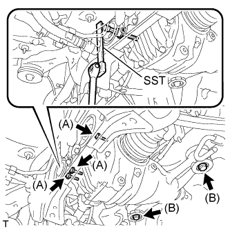
Using SST or a 12 mm socket hexagon wrench, remove the 3 bolts (A) from the rear No. 1 and No. 2 differential mount cushions.
- SST
- 09249-63010
-
Remove the 2 bolts (B).
-
Slowly lower the transmission jack. Then remove the rear differential mount stopper upper and lower, and rear differential carrier assembly from the rear suspension member.
Note
-
Do not drop the rear differential carrier assembly (with drive shaft).
-
When removing the rear differential carrier assembly (with drive shaft), do not damage the installation surface.
-
-
-
REMOVE REAR SUSPENSION MEMBER SUB-ASSEMBLY
-
REMOVE REAR SUSPENSION MEMBER DAMPER
-
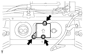
Remove the 3 bolts, and the rear suspension member damper.
-
-
REMOVE REAR NO. 1 DIFFERENTIAL MOUNT CUSHION
-
Pass SST bolts through the area shown in the illustration, and remove the mount cushion No. 1.
- SST
- 09316-12010
- 09570-24011
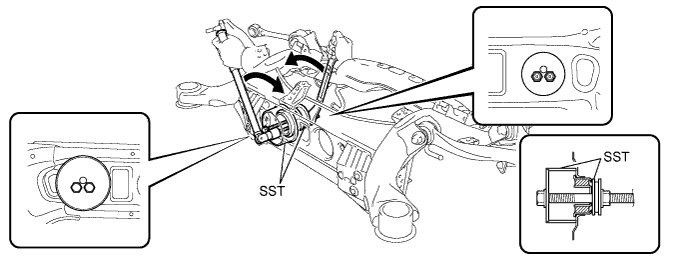
Note
-
When removing the mount cushion No. 1, do not allow the rear suspension member to contact SST (09316-12010).
-
Before using SST bolts, apply hypoid gear oil to their threads.
-
Be sure to combine SST properly.
-
Do not install SST bolts at an angle.
-
Make sure SST bolts are tightened equally.
-
-
REMOVE REAR NO. 2 DIFFERENTIAL MOUNT CUSHION
-
Pass SST bolt through the area shown in the illustration, and remove the mount cushion No. 2.
- SST
- 09316-12010
- 09570-24011
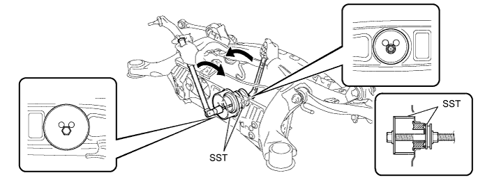
Note
-
When removing the mount cushion No. 2, do not allow the rear suspension member to contact SST (09316-12010).
-
Before using SST bolt, apply hypoid gear oil to its threads.
-
Be sure to combine SST properly.
-
Do not install SST bolts at an angle.
-