TRANSFER ASSEMBLY REMOVAL

-
REMOVE FRONT WHEEL
-
REMOVE V-BANK COVER SUB-ASSEMBLY
-
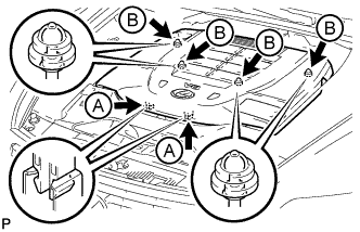
Using both hands, lift the rear side of the cover upwards to detach the 4 clips labeled B. Then slide the cover toward the front of the vehicle to detach the 2 clips labeled A and remove the V-bank cover sub-assembly.
Note
-
The V-bank cover sub-assembly may be damaged if its front and rear are lifted at the same time.
-
When detaching the clips labeled A, be sure to slide the cover toward the front of the vehicle.
-
-
-
REMOVE AIR CLEANER INLET COVER SUB-ASSEMBLY
-
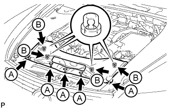
Remove the 5 clips labeled A.
-
Lift up the air cleaner inlet cover sub-assembly to detach the 4 clips labeled B, and remove the air cleaner inlet cover sub-assembly.
-
-
REMOVE NO. 1 AIR CLEANER INLET
-

Remove the 2 bolts.
-
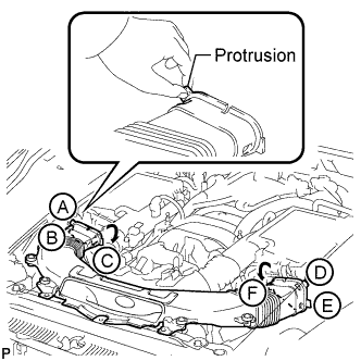
Hold the No. 1 air cleaner inlet by the protrusions labeled A and labeled B, and detach the connections.
-
Rotate the No. 1 air cleaner inlet as shown in the illustration to detach the protrusion labeled C.
-
Hold the No. 1 air cleaner inlet by the protrusions labeled D and labeled E, and detach the connections.
-
Rotate the No. 1 air cleaner inlet as shown in the illustration to detach the protrusion labeled F.
-
-
REMOVE ENGINE ROOM SIDE COVER RH
-
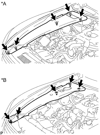
Text in Illustration *A for LHD *B for RHD Remove the 5 clips and engine room side cover RH.
-
-
REMOVE ENGINE ROOM SIDE COVER LH
-
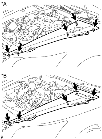
Text in Illustration *A for LHD *B for RHD Remove the 5 clips and engine room side cover LH.
-
-
REMOVE COWL TOP VENTILATOR LOUVER RH
-

Remove the 6 clips and cowl top ventilator louver RH.
-
-
REMOVE FRONT CENTER FLOOR COVER
-
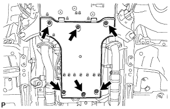
Remove the 3 screws, 2 bolts, clip and front center floor cover.
-
-
REMOVE NO. 2 ENGINE UNDER COVER
-
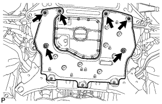
Remove the 4 screws, 2 clips and No. 2 engine under cover.
-
-
REMOVE NO. 1 ENGINE UNDER COVER
-
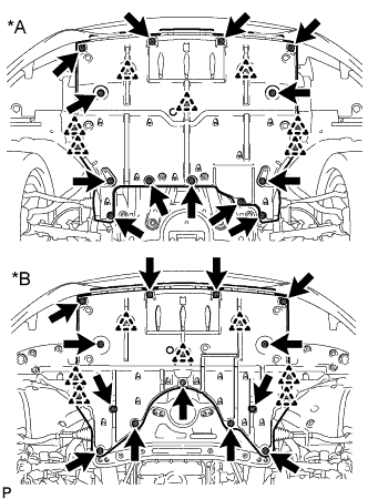
Text in Illustration *A for 2WD *B for AWD Remove the 13 screws, 7 clips and No. 1 engine under cover.
-
-
REMOVE FRONT LOWER SUSPENSION MEMBER PROTECTOR
-
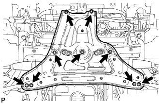
Remove the 9 bolts and front suspension member protector lower.
-
-
REMOVE FRONT EXHAUST PIPE ASSEMBLY
-
REMOVE PROPELLER SHAFT WITH CENTER BEARING ASSEMBLY
-
DISCONNECT FLOOR SHIFT GEAR SHIFTING ROD SUB-ASSEMBLY
-
Move the shift lever to N.
-
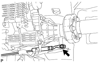
Remove the nut and disconnect the shifting rod from the connecting rod swivel.
-
-
LOOSEN FRONT PROPELLER SHAFT ASSEMBLY
-
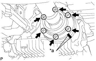
Text in Illustration *a Matchmark Put matchmarks on the transfer companion flange and front propeller shaft.
-
Using a 6 mm socket hexagon wrench, loosen the 6 bolts.
Note
Be careful not to damage the front propeller shaft.
-
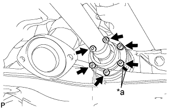
Text in Illustration *a Matchmark Put matchmarks on the front differential companion flange and front propeller shaft.
-
Using a 6 mm socket hexagon wrench, loosen the 6 bolts.
Note
Be careful not to damage the front propeller shaft.
-
-
DRAIN TRANSFER OIL
-
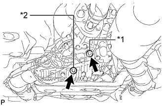
Text in Illustration *1 Filler plug *2 Drain plug Using a 10 mm hexagon wrench, remove the filler plug and gasket.
-
Using a 10 mm hexagon wrench, remove the drain plug and gasket, and drain the transfer oil.
-
-
REMOVE TRANSFER ASSEMBLY
-
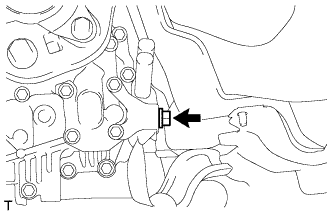
Remove the bolt and disconnect the ground cable.
-
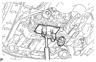
Using a jack and wooden blocks or equivalent, support the transfer.
Note
Do not set the wooden blocks or equivalent against the oil pan of the transmission.
-
Remove the 4 bolts, 5 nuts, No. 3 rear engine mounting insulator and rear engine mounting member.
-
While supporting the front propeller shaft assembly by hand, remove the 12 bolts and 4 constant velocity universal joint washers.
-
Remove the front propeller shaft assembly from each companion flange.
Note
Do not bend the front propeller shaft at an excessive angle.
-
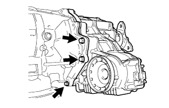
Remove the 3 bolts.
-
Install the rear engine mounting member and No. 3 rear engine mounting insulator with the 4 bolts and 5 nuts.
-
Set an engine lift and wooden blocks or equivalent against the rear engine mounting member and support the automatic transmission assembly.
Note
Do not set the wooden blocks or equivalent against the oil pan of the transmission.
-
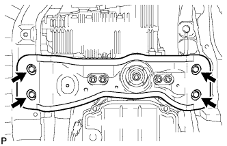
Remove the 4 bolts and disconnect the rear engine mounting member.
-
Slowly tilt the automatic transmission assembly away from the vehicle.
Note
Be careful of the exhaust manifold and wire harnesses when tilting the transmission.
-
Make sure the wooden blocks or equivalent are set securely against the transfer with the jack.
-
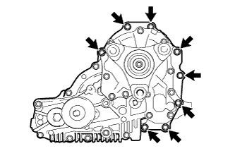
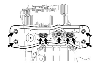
Remove the 8 bolts and transfer.
Note
-
Do not damage the oil seal.
-
Be careful not to drop the transfer assembly.
-
Be sure to perform this procedure with several people as the transfer assembly is very heavy.
-
-
Connect the rear engine mounting member with the 4 bolts.
-