AUTOMATIC TRANSMISSION SYSTEM, Diagnostic DTC:P0748, P0778, P0798, P2810, P2819

| DTC Code | DTC Name |
|---|---|
| P0748 | Pressure Control Solenoid "A" Electrical (Shift Solenoid Valve SL1) |
| P0778 | Pressure Control Solenoid "B" Electrical (Shift Solenoid Valve SL2) |
| P0798 | Pressure Control Solenoid "C" Electrical (Shift Solenoid Valve SL3) |
| P2810 | Pressure Control Solenoid "G" Electrical (Shift Solenoid Valve SL4) |
| P2819 | Pressure Control Solenoid "H" Electrical (Shift Solenoid Valve SL5) |
DESCRIPTION
Based on the on-off combinations of shift solenoid valves SL1, 2, 3, 4 and 5, the TCM performs gear shifts from 1st gear to 8th gear.
If a circuit related to a solenoid valve is open or shorted, the TCM uses the fail-safe function to turn other solenoid valves on or off. If all solenoid valves are malfunctioning, only the mechanical fluid pressure circuit will function and the system will change to a manual transmission. If an open or short has occurred, the TCM cuts power to the malfunctioning solenoid valve.
| DTC Code | DTC Detection Condition
|
Trouble Area |
|---|---|---|
| P0748 |
|
|
| P0778 |
|
|
| P0798 |
|
|
| P2810 |
|
|
| P2819 |
|
|
MONITOR DESCRIPTION
These DTCs indicate an open or short in the shift solenoid valve SL1, 2, 3, 4 or 5 circuit. The TCM commands gear shifts by turning the shift solenoid valves on/off. When there is an open or short circuit in any shift solenoid valve circuit, the TCM detects the problem, illuminates the MIL and stores the DTC. Also, the TCM performs the fail-safe function and turns the other normal shift solenoid valves on/off. In case of an open or short circuit, the TCM stops sending current to the open or short-circuited solenoid.
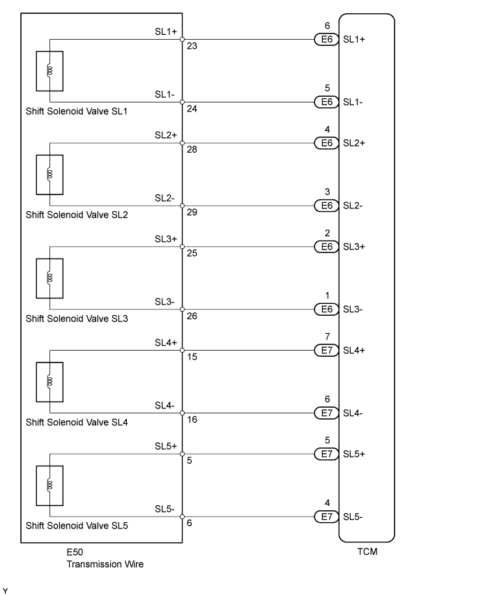
WIRING DIAGRAM
INSPECTION PROCEDURE
Tech Tips
Shift solenoid valves SL1, 2, 3, 4 and 5 turn on/off normally when the shift lever is in D.
| Gear Position | 1st | 2nd | 3rd | 4th | 5th | 6th | 7th | 8th |
| Shift Solenoid Valve SL1 | ON | ON | ON | ON | ON | OFF | OFF | OFF |
| Shift Solenoid Valve SL2 | OFF | OFF | OFF | OFF | ON | ON | ON | ON |
| Shift Solenoid Valve SL3 | OFF | OFF | ON | OFF | OFF | OFF | ON | OFF |
| Shift Solenoid Valve SL4 | OFF | OFF | OFF | ON | OFF | ON | OFF | OFF |
| Shift Solenoid Valve SL5 | OFF | ON | OFF | OFF | OFF | OFF | OFF | ON |
PROCEDURE
-
CHECK HARNESS AND TRANSMISSION WIRE (TRANSMISSION WIRE - TCM, TRANSMISSION WIRE (SHIFT SOLENOID VALVE SL1, 2, 3, 4 AND 5))
-
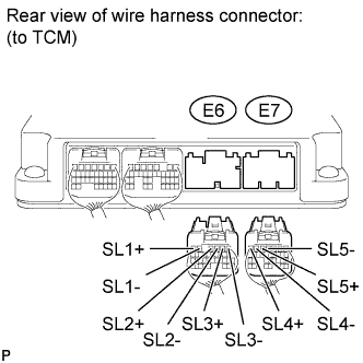
Disconnect the E6 and E7 TCM connectors.
-
Measure the resistance according to the value(s) in the table below.
Standard Resistance Tester Connection Condition Specified Condition E6-6 (SL1+) - E6-5 (SL1-) Always 5.0 to 5.6 Ω E6-4 (SL2+) - E6-3 (SL2-) Always 5.0 to 5.6 Ω E6-2 (SL3+) - E6-1 (SL3-) Always 5.0 to 5.6 Ω E7-7 (SL4+) - E7-6 (SL4-) Always 5.0 to 5.6 Ω E7-5 (SL5+) - E7-4 (SL5-) Always 5.0 to 5.6 Ω E6-6 (SL1+) or E6-5 (SL1-) - Body ground Always 10 kΩ or higher E6-4 (SL2+) or E6-3 (SL2-) - Body ground Always 10 kΩ or higher E6-2 (SL3+) or E6-1 (SL3-) - Body ground Always 10 kΩ or higher E7-7 (SL4+) or E7-6 (SL4-) - Body ground Always 10 kΩ or higher E7-5 (SL5+) or E7-4 (SL5-) - Body ground Always 10 kΩ or higher
NG 
CHECK HARNESS AND CONNECTOR (TRANSMISSION WIRE - TCM) Click here
OK 
-
-
REPLACE TCM
-
Replace the TCM Click here.
NEXT 
PERFORM A/T CODE REGISTRATION Click here
-
-
CHECK HARNESS AND CONNECTOR (TRANSMISSION WIRE - TCM)
-
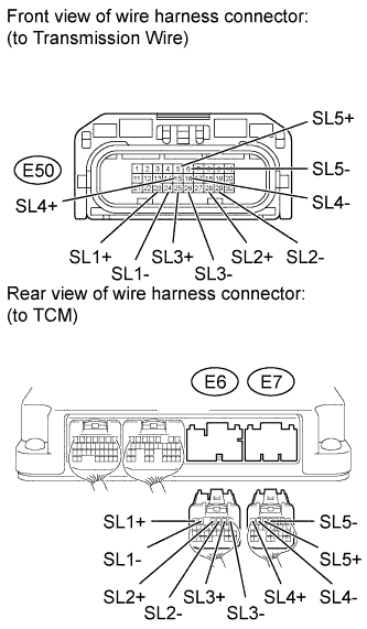
Disconnect the E50 transmission wire connector.
-
Disconnect the E6 and E7 TCM connectors.
-
Measure the resistance according to the value(s) in the table below.
Standard Resistance Tester Connection Condition Specified Condition E50-23 (SL1+) - E6-6 (SL1+) Always Below 1 Ω E50-24 (SL1-) - E6-5 (SL1-) Always Below 1 Ω E50-28 (SL2+) - E6-4 (SL2+) Always Below 1 Ω E50-29 (SL2-) - E6-3 (SL2-) Always Below 1 Ω E50-25 (SL3+) - E6-2 (SL3+) Always Below 1 Ω E50-26 (SL3-) - E6-1 (SL3-) Always Below 1 Ω E50-15 (SL4+) - E7-7 (SL4+) Always Below 1 Ω E50-16 (SL4-) - E7-6 (SL4-) Always Below 1 Ω E50-5 (SL5+) - E7-5 (SL5+) Always Below 1 Ω E50-6 (SL5-) - E7-4 (SL5-) Always Below 1 Ω E50-23 (SL1+) or E6-6 (SL1+) - Body ground Always 10 kΩ or higher E50-24 (SL1-) or E6-5 (SL1-) - Body ground Always 10 kΩ or higher E50-28 (SL2+) or E6-4 (SL2+) - Body ground Always 10 kΩ or higher E50-29 (SL2-) or E6-3 (SL2-) - Body ground Always 10 kΩ or higher E50-25 (SL3+) or E6-2 (SL3+) - Body ground Always 10 kΩ or higher E50-26 (SL3-) or E6-1 (SL3-) - Body ground Always 10 kΩ or higher E50-15 (SL4+) or E7-7 (SL4+) - Body ground Always 10 kΩ or higher E50-16 (SL4-) or E7-6 (SL4-) - Body ground Always 10 kΩ or higher E50-5 (SL5+) or E7-5 (SL5+) - Body ground Always 10 kΩ or higher E50-6 (SL5-) or E7-4 (SL5-) - Body ground Always 10 kΩ or higher
NG 
REPAIR OR REPLACE HARNESS OR CONNECTOR
OK
-
-
INSPECT SHIFT SOLENOID VALVE SL1, 2, 3, 4 AND 5
-
Remove the shift solenoid valves Click here.
-
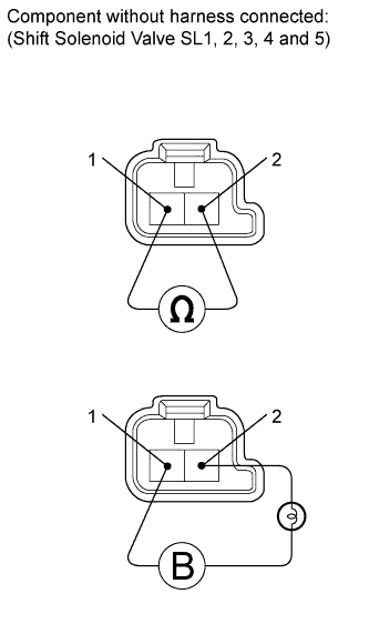
Measure the resistance according to the value(s) in the table below.
Standard Resistance Tester Connection Condition Specified Condition Terminal 1 of shift solenoid valve SL1 - Terminal 2 20°C (68°F) 5.0 to 5.6 Ω Terminal 1 of shift solenoid valve SL2 - Terminal 2 20°C (68°F) 5.0 to 5.6 Ω Terminal 1 of shift solenoid valve SL3 - Terminal 2 20°C (68°F) 5.0 to 5.6 Ω Terminal 1 of shift solenoid valve SL4 - Terminal 2 20°C (68°F) 5.0 to 5.6 Ω Terminal 1 of shift solenoid valve SL5 - Terminal 2 20°C (68°F) 5.0 to 5.6 Ω -
Connect the battery's positive (+) lead with a 21 W bulb to terminal 2 and the negative (-) lead to terminal 1 of the solenoid valve connector. Then check that the valve moves and makes an operating noise.
OK Valve moves and makes operating noise.
NG
REPLACE SHIFT SOLENOID VALVE Click here
OK
REPAIR OR REPLACE TRANSMISSION WIRE Click here
-