AUTOMATIC TRANSMISSION SYSTEM, Diagnostic DTC:P0711

| DTC Code | DTC Name |
|---|---|
| P0711 | Transmission Fluid Temperature Sensor "A" Performance |
DESCRIPTION
Refer to DTC P0712 Click here.
| DTC Code | DTC Detection Condition
|
Trouble Area |
|---|---|---|
| P0711 |
|
|
| P0711 |
|
|
MONITOR DESCRIPTION
This DTC indicates that there is a problem with output from the ATF temperature sensor and that the sensor itself is defective. The ATF temperature sensor converts the ATF temperature to an electrical resistance value. Based on the resistance, the TCM determines the ATF temperature and detects open or short circuits in the ATF temperature sensor circuit or faults in the ATF temperature sensor.
After running the vehicle for a certain period, the ATF temperature should increase. If the ATF temperature is below 20°C (68°F), or 110°C (230°F) or higher after driving the vehicle for a certain period, the TCM interprets this as a fault, illuminates the MIL and stores the DTC.
WIRING DIAGRAM
Refer to DTC P0712 Click here.
INSPECTION PROCEDURE
Refer to DTC P0712 Click here.
PROCEDURE
-
CHECK DTC OUTPUT (IN ADDITION TO DTC P0711 AND P0713)
-
Connect the intelligent tester to the DLC3.
-
Turn the engine switch on (IG).
-
Turn the intelligent tester on.
-
Enter the following menus: Powertrain / ECT / Trouble Codes.
-
Read the DTCs using the intelligent tester.
Result Display (DTC output) Proceed to Only P0711 is output A P0711 and P0713 are output B DTCs other than P0711 and P0713 are output C Tech Tips
If any other codes besides P0711 and P0713 are output, perform troubleshooting for those DTCs first.
B 
GO TO DTC P0713 FLOWCHART Click here
C
GO TO DTC CHART Click here
A 
-
-
CHECK TRANSMISSION FLUID LEVEL
-
Check the transmission fluid level Click here.
OK Automatic transmission fluid level is correct.
NG
ADJUST FLUID LEVEL Click here
OK
-
-
CHECK HARNESS AND TRANSMISSION WIRE (TRANSMISSION WIRE - TCM, TRANSMISSION WIRE (ATF TEMPERATURE SENSOR))
-
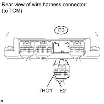
Disconnect the E6 TCM connector.
-
Measure the resistance according to the value(s) in the table below.
Standard Resistance Tester Connection Condition Specified Condition E6-27 (THO1) - E6-35 (E2) ATF temperature 10°C (50°F) 5.8 to 7.1 kΩ E6-27 (THO1) - E6-35 (E2) ATF temperature 25°C (77°F) 2.5 to 4.5 kΩ E6-27 (THO1) - E6-35 (E2) ATF temperature 110°C (230°F) 231 to 263 Ω Tech Tips
The resistance value for the 25°C (77°F) ATF temperature condition is a reference value.
-
Measure the resistance according to the value(s) in the table below.
Standard Resistance Tester Connection Condition Specified Condition E6-27 (THO1) - Body ground Always 10 kΩ or higher E6-35 (E2) - Body ground Always 10 kΩ or higher E6-27 (THO1) or E6-35 (E2) - Body ground Always 10 kΩ or higher
NG 
CHECK HARNESS AND CONNECTOR (TRANSMISSION WIRE - TCM) Click here
OK
-
-
REPLACE TCM
-
Replace the TCM Click here.
NEXT 
PERFORM A/T CODE REGISTRATION Click here
-
-
CHECK HARNESS AND CONNECTOR (TRANSMISSION WIRE - TCM)
-
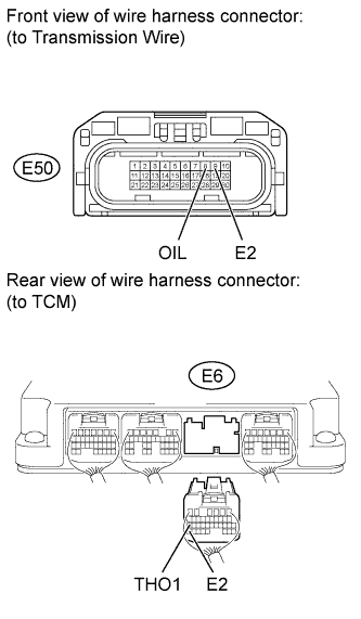
Disconnect the E50 transmission wire connector.
-
Disconnect the E6 TCM connector.
-
Measure the resistance according to the value(s) in the table below.
Standard Resistance Tester Connection Condition Specified Condition E50-8 (OIL) - E6-27 (THO1) Always Below 1 Ω E50-9 (E2) - E6-35 (E2) Always Below 1 Ω
NG
REPAIR OR REPLACE HARNESS OR CONNECTOR
OK
REPAIR OR REPLACE TRANSMISSION WIRE Click here
-