AUTOMATIC TRANSMISSION SYSTEM, Diagnostic DTC:P0500, P0502, P0503

| DTC Code | DTC Name |
|---|---|
| P0500 | Vehicle Speed Sensor "A" |
| P0502 | Vehicle Speed Sensor "A" Circuit Low |
| P0503 | Vehicle Speed Sensor "A" Intermittent / Erratic / High |
DESCRIPTION
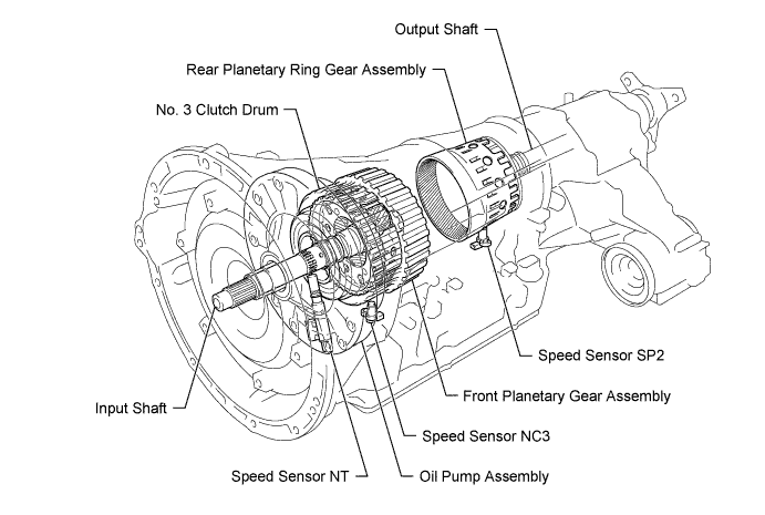
The speed sensor (SP2) detects the output shaft rotation speed and inputs it into the TCM as a signal.
Based on the speed sensor (NT) signal and the speed sensor (SP2) signal, the TCM controls engine torque and shift timing.
| DTC Code | DTC Detection Condition
|
Trouble Area |
|---|---|---|
| P0500 |
|
|
| P0502 |
|
|
| P0503 |
|
|
MONITOR DESCRIPTION
The NT terminal of the TCM detects a pulse signal from the speed sensor (NT) (input rpm). The TCM calculates gear shifts comparing the signal from the speed sensor (NT) with that from the speed sensor (NC3).
If there is no signal from the speed sensor (SP2), or if the speed sensor (SP2) voltage is below 0.1 V or higher than 1.9 V, the TCM interprets this as a fault, illuminates the MIL and stores a DTC.
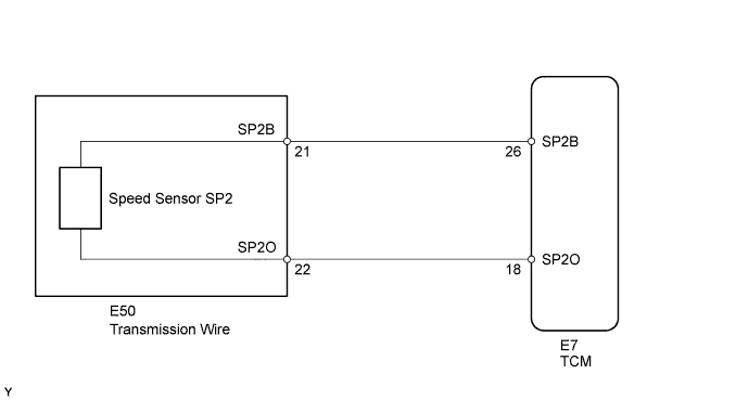
WIRING DIAGRAM
INSPECTION PROCEDURE
Tech Tips
Using the intelligent tester to read the Data List allows the values or states of switches, sensors, actuators and other items to be read without removing any parts. This non-intrusive inspection can be very useful because intermittent conditions or signals may be discovered before parts or wiring is disturbed. Reading the Data List information early in troubleshooting is one way to save diagnostic time.
Note
In the table below, the values listed under "Normal Condition" are reference values. Do not depend solely on these reference values when deciding whether a part is faulty or not.
-
Warm up the engine.
-
Turn the engine switch off.
-
Connect the intelligent tester to the DLC3.
-
Turn the engine switch on (IG).
-
Turn the intelligent tester on.
-
Enter the following menus: Powertrain / ECT / Data List.
-
According to the display on the tester, read the Data List.
TCM Tester Display Measurement Item/Range Normal Condition Diagnostic Note SPD (SP2) Output shaft speed/
Min.: 0 km/h (0 mph)
Max.: 255 km/h (158 mph)
Vehicle stopped: 0 km/h (0 mph)
(output shaft speed equal to vehicle speed)
- Tech Tips
-
SPD (SP2) is always 0 while driving: Open or short in the sensor or circuit.
-
SPD (SP2) is always more than 0 and less than 300 rpm while driving the vehicle at 50 km/h (31 mph) or more: Sensor trouble, improper installation, or intermittent connection trouble of the circuit.
-
PROCEDURE
-
CHECK SPEED SENSOR TERMINAL (SP2 TERMINAL)
-
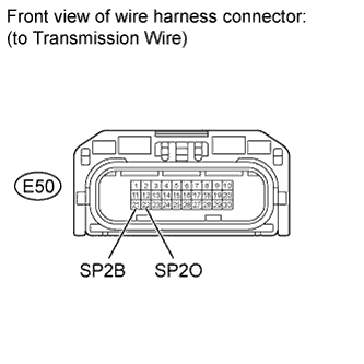
Disconnect the E50 transmission wire connector.
-
Turn the engine switch on (IG).
-
Measure the voltage according to the value(s) in the table below.
Standard Voltage Tester Connection Switch Condition Specified Condition E50-21 (SP2B) - Body ground Engine switch on (IG) 11 to 14 V -
Turn the engine switch off.
-
Measure the resistance according to the value(s) in the table below.
Standard Resistance Tester Connection Condition Specified Condition E50-22 (SP2O) - Body ground Always 100 Ω
NG 
CHECK HARNESS AND CONNECTOR (TRANSMISSION WIRE - TCM) Click here
OK 
-
-
INSPECT TRANSMISSION WIRE (SPEED SENSOR SP2)
-
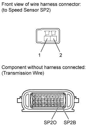
Disconnect the speed sensor (SP2) connector.
-
Disconnect the E50 transmission wire connector.
-
Measure the resistance according to the value(s) in the table below.
Standard Resistance Tester Connection Condition Specified Condition Terminal 1 of the speed sensor (SP2) connector - 21 (SP2B) Always Below 1 Ω Terminal 2 of the speed sensor (SP2) connector - 22 (SP2O) Always Below 1 Ω Terminal 1 of the speed sensor (SP2) connector or 21 (SP2B) - Body ground Always 10 kΩ or higher Terminal 2 of the speed sensor (SP2) connector or 22 (SP2O) - Body ground Always 10 kΩ or higher
NG 
REPAIR OR REPLACE TRANSMISSION WIRE Click here
OK 
REPLACE SPEED SENSOR Click here
-
-
CHECK HARNESS AND CONNECTOR (TRANSMISSION WIRE - TCM)
-
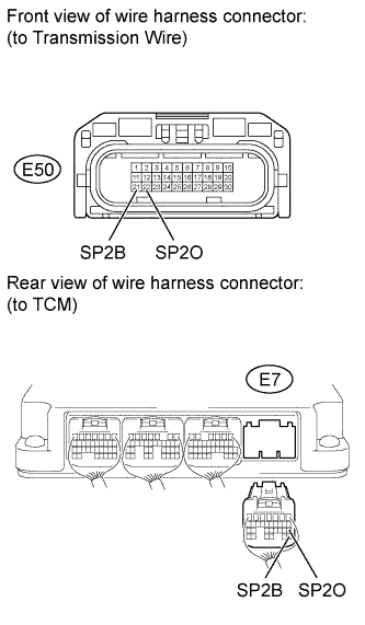
Disconnect the E50 transmission wire connector.
-
Disconnect the E7 TCM connector.
-
Measure the resistance according to the value(s) in the table below.
Standard Resistance Tester Connection Condition Specified Condition E50-21 (SP2B) - E7-26 (SP2B) Always Below 1 Ω E50-22 (SP2O) - E7-18 (SP2O) Always Below 1 Ω E50-21 (SP2B) or E7-26 (SP2B) - Body ground Always 10 kΩ or higher E50-22 (SP2O) or E7-18 (SP2O) - Body ground Always 10 kΩ or higher
NG
REPAIR OR REPLACE HARNESS OR CONNECTOR
OK
-
-
REPLACE TCM
-
Replace the TCM Click here.
NEXT
PERFORM A/T CODE REGISTRATION Click here
-